

Hardware Manual - RTD Embedded Technologies, Inc.
Hardware Manual - RTD Embedded Technologies, Inc.
Hardware Manual - RTD Embedded Technologies, Inc.

You also want an ePaper? Increase the reach of your titles
YUMPU automatically turns print PDFs into web optimized ePapers that Google loves.
Port 0, Bit Programmable Digital I/O<br />
The eight Port 0 digital lines are individually set for input or output by writing to the Port 0 Direction Register at<br />
BA + 0x1Ch. The input lines are read and the output lines are written at BA + 0x18h.<br />
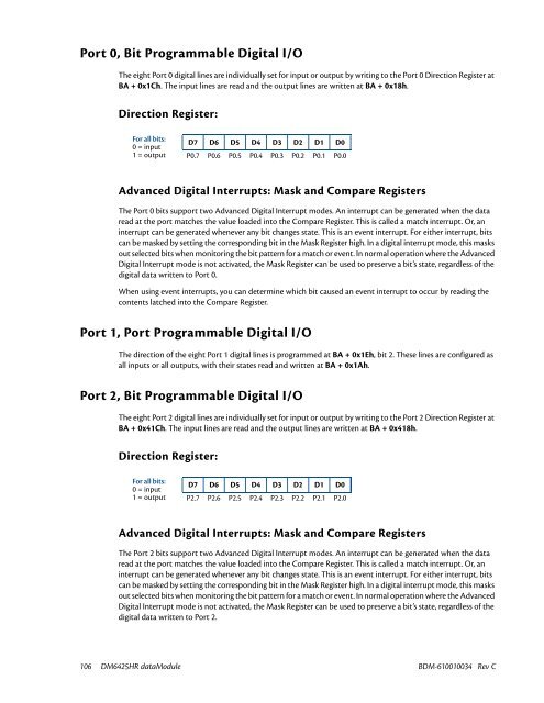
Direction Register:<br />
For all bits:<br />
0 = input<br />
1 = output<br />
D7 D6 D5 D4 D3 D2 D1 D0<br />
P0.7 P0.6 P0.5 P0.4 P0.3 P0.2 P0.1 P0.0<br />
Advanced Digital Interrupts: Mask and Compare Registers<br />
The Port 0 bits support two Advanced Digital Interrupt modes. An interrupt can be generated when the data<br />
read at the port matches the value loaded into the Compare Register. This is called a match interrupt. Or, an<br />
interrupt can be generated whenever any bit changes state. This is an event interrupt. For either interrupt, bits<br />
can be masked by setting the corresponding bit in the Mask Register high. In a digital interrupt mode, this masks<br />
out selected bits when monitoring the bit pattern for a match or event. In normal operation where the Advanced<br />
Digital Interrupt mode is not activated, the Mask Register can be used to preserve a bit’s state, regardless of the<br />
digital data written to Port 0.<br />
When using event interrupts, you can determine which bit caused an event interrupt to occur by reading the<br />
contents latched into the Compare Register.<br />
Port 1, Port Programmable Digital I/O<br />
The direction of the eight Port 1 digital lines is programmed at BA + 0x1Eh, bit 2. These lines are configured as<br />
all inputs or all outputs, with their states read and written at BA + 0x1Ah.<br />
Port 2, Bit Programmable Digital I/O<br />
The eight Port 2 digital lines are individually set for input or output by writing to the Port 2 Direction Register at<br />
BA + 0x41Ch. The input lines are read and the output lines are written at BA + 0x418h.<br />
Direction Register:<br />
For all bits:<br />
0 = input<br />
1 = output<br />
D7 D6 D5 D4 D3 D2 D1 D0<br />
P2.7 P2.6 P2.5 P2.4 P2.3 P2.2 P2.1 P2.0<br />
Advanced Digital Interrupts: Mask and Compare Registers<br />
The Port 2 bits support two Advanced Digital Interrupt modes. An interrupt can be generated when the data<br />
read at the port matches the value loaded into the Compare Register. This is called a match interrupt. Or, an<br />
interrupt can be generated whenever any bit changes state. This is an event interrupt. For either interrupt, bits<br />
can be masked by setting the corresponding bit in the Mask Register high. In a digital interrupt mode, this masks<br />
out selected bits when monitoring the bit pattern for a match or event. In normal operation where the Advanced<br />
Digital Interrupt mode is not activated, the Mask Register can be used to preserve a bit’s state, regardless of the<br />
digital data written to Port 2.<br />
106 DM6425HR dataModule BDM-610010034 Rev C


