Hardware Manual - RTD Embedded Technologies, Inc.
Hardware Manual - RTD Embedded Technologies, Inc.
Hardware Manual - RTD Embedded Technologies, Inc.
You also want an ePaper? Increase the reach of your titles
YUMPU automatically turns print PDFs into web optimized ePapers that Google loves.
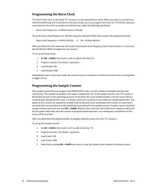
Programming the Burst Clock<br />
The third 16-bit timer in the Clock TC, Counter 2, is the onboard burst clock. When you want to use the burst<br />
clock for performing A/D conversions in the burst mode, you must program the clock rate. To find the value you<br />
must load into the clock to produce the desired rate, make the following calculation:<br />
Burst clock frequency = 8 MHz/Counter 2 Divider<br />
To set the burst clock frequency at 100 kHz using the onboard 8 MHz clock source, this equation becomes:<br />
Burst clock frequency = 8 MHz/100 kHz ⇒ 80 = 8 MHz/100 kHz<br />
After you determine the value that will result in the desired clock frequency, load it into Counter 2. In this case,<br />
decimal 80 (hex 0050) is loaded into the counter.<br />
To set up the burst clock:<br />
1. Set BA + 0x02h, bits 6 and 5 to 00 to talk to the Clock TC.<br />
2. Program Counter 2 for Mode 2 operation.<br />
3. Load Divider LSB.<br />
4. Load Divider MSB.<br />
Depending on your conversion mode, the counter start its countdown and the burst clock starts running when<br />
a trigger occurs.<br />
Programming the Sample Counter<br />
The sample counter lets you program the DM6425HR to take a certain number of samples and then halt<br />
conversions. The number of samples to be taken is loaded into the 16-bit sample counter, User TC Counter 2.<br />
Recall that because of the operating structure of the 8254, the count loaded initially is not the count which is<br />
counted down during the first cycle. A software correction is used as an easy means to compensate for this. Two<br />
pulses of the counter are required to actually load the desired count and prepare the counter to count down<br />
correctly (this can be looked at as the initialization procedure for the sample counter). A pulse is sent to the 8254<br />
sample counter each time you read BA + 0x0Eh. Without this correction, the initial count sequence will be off<br />
by two pulses. Note that once the counter is properly loaded and starts, any subsequent countdowns of this<br />
count will be accurate.<br />
After you determine the desired number of samples, load the count into User TC Counter 2.<br />
To set up the sample counter:<br />
1. Set BA + 0x02h, bits 6 and 5 to 01 to talk to the User TC.<br />
2. Program Counter 2 for Mode 2 operation.<br />
3. Load Count LSB.<br />
4. Load Count MSB.<br />
5. Pulse line by reading BA + 0x0Eh two times so that the loaded count matches the desired count.<br />
78 DM6425HR dataModule BDM-610010034 Rev C


