

Hardware Manual - RTD Embedded Technologies, Inc.
Hardware Manual - RTD Embedded Technologies, Inc.
Hardware Manual - RTD Embedded Technologies, Inc.

Create successful ePaper yourself
Turn your PDF publications into a flip-book with our unique Google optimized e-Paper software.
Using the Sample Counter to Create Large Data Arrays<br />
The 16-bit sample counter allows you to take up to 65,536 samples before the count reaches 0 and sampling is<br />
halted. Suppose, however, you want to take 100,000 samples and stop. The DM6425HR provides a bit in the<br />
Control Register at BA + 0x02h which allows you to use the sample counter to take more than 65,536 samples<br />
in a conversion sequence.<br />
Bit 7 in the Control Register, the sample counter stop enable bit, can be set to 1 to allow the sample counter to<br />
continuously cycle through the loaded count until the stop enable bit is set to 0, which then causes the sample<br />
counter to stop at the end of the current cycle. Let’s look back at our example where we want to take 100,000<br />
readings. First, we must divide 100,000 by a whole number that gives a result of less than 65,536. In our example,<br />
we can divide as follows:<br />
Sample Counter Count = 100,000 / 2 = 50,000<br />
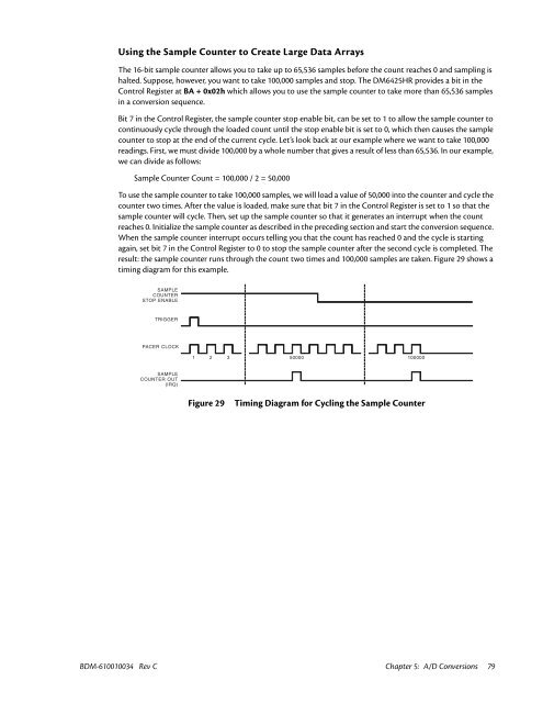
To use the sample counter to take 100,000 samples, we will load a value of 50,000 into the counter and cycle the<br />
counter two times. After the value is loaded, make sure that bit 7 in the Control Register is set to 1 so that the<br />
sample counter will cycle. Then, set up the sample counter so that it generates an interrupt when the count<br />
reaches 0. Initialize the sample counter as described in the preceding section and start the conversion sequence.<br />
When the sample counter interrupt occurs telling you that the count has reached 0 and the cycle is starting<br />
again, set bit 7 in the Control Register to 0 to stop the sample counter after the second cycle is completed. The<br />
result: the sample counter runs through the count two times and 100,000 samples are taken. Figure 29 shows a<br />
timing diagram for this example.<br />
SAMPLE<br />
COUNTER<br />
STOP ENABLE<br />
TRIGGER<br />
PACER CLOCK<br />
1 2 3 50000 100000<br />
SAMPLE<br />
COUNTER OUT<br />
(IRQ)<br />
Figure 29<br />
Timing Diagram for Cycling the Sample Counter<br />
BDM-610010034 Rev C Chapter 5: A/D Conversions 79


