

Hardware Manual - RTD Embedded Technologies, Inc.
Hardware Manual - RTD Embedded Technologies, Inc.
Hardware Manual - RTD Embedded Technologies, Inc.

Create successful ePaper yourself
Turn your PDF publications into a flip-book with our unique Google optimized e-Paper software.
JS1, JS2, JS3, and JS4—Pull-Up/Pull-Down Resistors on Digital I/O Lines<br />
The DM6425HR has 32 TTL/CMOS compatible digital I/O lines that can be interfaced with external devices.<br />
These lines are divided into four groups: Port 0 has eight bit programmable lines, advanced interrupt modes, and<br />
bit masking, Port 1 is byte direction programmable, Port 2 is output, and Port 3 is latched input. Resistors are<br />
connected to these lines and can be configured as either pull-up or pull-down resistors.<br />
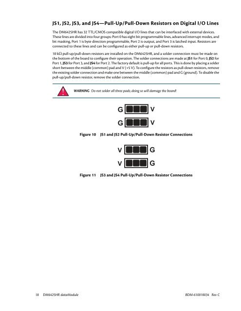
10 kΩ pull-up/pull-down resistors are installed on the DM6425HR, and a solder connection must be made on<br />
the bottom of the board to configure their operation. The solder connections are made at JS1 for Port 0, JS2 for<br />
Port 1, JS3 for Port 3, and JS4 for Port 2. The factory default is pull-up for all ports. This is done by placing a solder<br />
short between the middle (common) pad and V (+5 V). To configure the resistors as pull-down resistors, remove<br />
the existing solder connection and make one between the middle (common) pad and G (ground). To disable the<br />
pull-up/pull-down resistor, remove the solder connection.<br />
WARNING Do not solder all three pads; doing so will damage the board!<br />
G<br />
G<br />
V<br />
V<br />
Figure 10<br />
JS1 and JS2 Pull-Up/Pull-Down Resistor Connections<br />
V<br />
V<br />
G<br />
G<br />
Figure 11<br />
JS3 and JS4 Pull-Up/Pull-Down Resistor Connections<br />
18 DM6425HR dataModule BDM-610010034 Rev C


