Hardware Manual - RTD Embedded Technologies, Inc.
Hardware Manual - RTD Embedded Technologies, Inc.
Hardware Manual - RTD Embedded Technologies, Inc.
You also want an ePaper? Increase the reach of your titles
YUMPU automatically turns print PDFs into web optimized ePapers that Google loves.
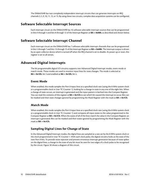
The DM6425HR has two completely independent interrupt circuits that can generate interrupts on IRQ<br />
channels 3, 5, 9, 10, 11, 12, or 15. By using these two circuits, complex data acquisition systems can be configured.<br />
Software Selectable Interrupt Sources<br />
Each interrupt circuit on the DM6425HR has 16 software selectable interrupt sources that can be programmed<br />
in bits 0 through 4 and bits 8 through 12 of the Interrupt Register at BA + 0x08h, as described and shown below.<br />
Software Selectable Interrupt Channel<br />
Each interrupt circuit on the DM6425HR has 7 software selectable interrupt channels that can be programmed<br />
in bits 5 through 7 and bits 13 through 15 of the Interrupt Register at BA + 0x08h. The interrupt output is driven<br />
by an open collector device which is turned off when the IRQ channel is set to disable. At power up or reset, this<br />
register is set to all zeroes.<br />
Advanced Digital Interrupts<br />
The bit programmable digital I/O circuitry supports two Advanced Digital Interrupt modes, event mode or<br />
match mode. These modes are used to monitor input lines for state changes. The mode is selected at<br />
BA + 0x1Eh, bit 3 and enabled at BA + 0x1Eh, bit 4.<br />
Event Mode<br />
When enabled, this mode samples the Port 0 input lines at a specified clock rate (using the 8 MHz system clock<br />
or a programmable clock in User TC Counter 1), looking for a change in state in any one of the eight bits. When<br />
a change of state occurs, an interrupt is generated and the input pattern is latched into the Compare Register.<br />
You can read the contents of this register at BA + 0x1Ch to see which bit caused the interrupt to occur. Bits can<br />
be masked and their state changes ignored by programming the Mask Register with the mask at BA + 0x1Ch.<br />
Match Mode<br />
When enabled, this mode samples the Port 0 input lines at a specified clock rate (using the 8 MHz system clock<br />
or a programmable clock in User TC Counter 1) and compares all input states to the value programmed in the<br />
Compare Register at BA + 0x1Ch. When the states of all of the lines match the value in the Compare Register, an<br />
interrupt is generated. Bits can be masked and their states ignored by programming the Mask Register with the<br />
mask at BA + 0x1Ch.<br />
Sampling Digital Lines for Change of State<br />
In the Advanced Digital Interrupt modes, the digital lines are sampled at a rate set by the 8 MHz system clock or<br />
the clock programmed in User TC Counter 1. With each clock pulse, the digital circuitry looks at the state of the<br />
next Port 0 bits. To provide noise rejection and prevent erroneous interrupt generation because of noise spikes<br />
on the digital lines, a change in the state of any bit must be seen for two edges of a clock pulse to be recognized<br />
by the circuit. Figure 30 shows a diagram of this circuit.<br />
92 DM6425HR dataModule BDM-610010034 Rev C


