warning!
warning!
warning!

You also want an ePaper? Increase the reach of your titles
YUMPU automatically turns print PDFs into web optimized ePapers that Google loves.
12. SHIFT LEVER<br />
In the Test Mode, if the SHIFT LEVER's SW can not be inputted satisfactorily, replace the<br />
Switch. Apply greasing to the Mechanism's sliding portion once every 3 months.<br />
When performing the above work, remove the Shift Lever Unit.<br />
WARNING!<br />
Before starting to work, ensure that the Power SW is OFF. Failure to observe<br />
this can cause electric shock and short circuit hazards.<br />
Use care so as not to damage wirings. Damaged wiring can cause electric<br />
shock and short circuit hazards.<br />
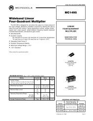
12-1 REMOVING THE SHIFT LEVER<br />
TAMPERPROOF SCREW (4),black<br />
Turn the Power SW off.<br />
Remove the 4 Tamperproof<br />
Screws to lift the Shift Lever<br />
Unit.<br />
Disconnect the Connector to<br />
remove the Shift Lever Unit.<br />
When reinstalling, follow the<br />
procedure opposite as when<br />
removing. At this time, ensure<br />
that "DOWN" display appears<br />
on the upper part as shown.<br />
After reinstalling, be sure to check INPUT TEST in the<br />
test mode. (See 10-3B.)<br />
TAPPING SCREW (2)<br />
M3×16<br />
GREASING<br />
FIG. 12. 1<br />
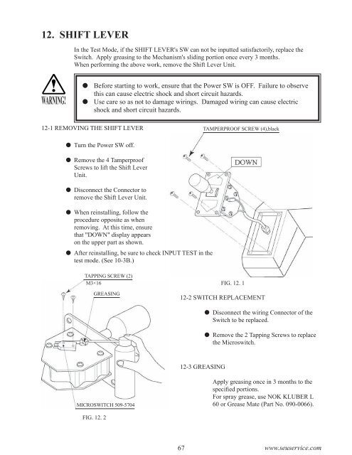
12-2 SWITCH REPLACEMENT<br />
Disconnect the wiring Connector of the<br />
Switch to be replaced.<br />
Remove the 2 Tapping Screws to replace<br />
the Microswitch.<br />
12-3 GREASING<br />
MICROSWITCH 509-5704<br />
Apply greasing once in 3 months to the<br />
specified portions.<br />
For spray grease, use NOK KLUBER L<br />
60 or Grease Mate (Part No. 090-0066).<br />
FIG. 12. 2<br />
67 www.seuservice.com