warning!
warning!
warning!

Create successful ePaper yourself
Turn your PDF publications into a flip-book with our unique Google optimized e-Paper software.
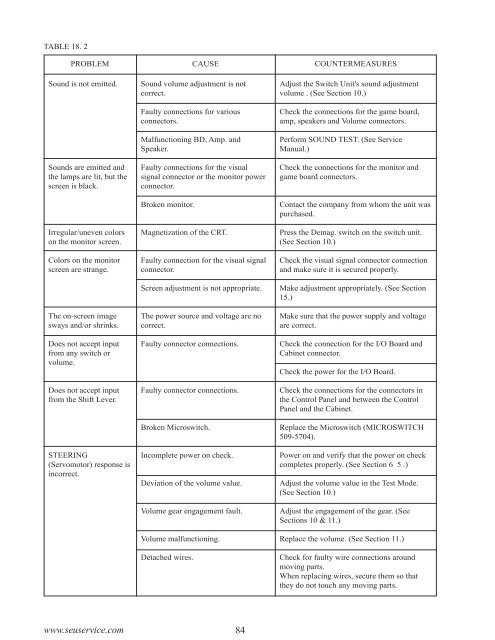
TABLE 18. 2<br />
PROBLEM CAUSE COUNTERMEASURES<br />
Sound is not emitted.<br />
Sounds are emitted and<br />
the lamps are lit, but the<br />
screen is black.<br />
Irregular/uneven colors<br />
on the monitor screen.<br />
Colors on the monitor<br />
screen are strange.<br />
The on-screen image<br />
sways and/or shrinks.<br />
Does not accept input<br />
from any switch or<br />
volume.<br />
Does not accept input<br />
from the Shift Lever.<br />
STEERING<br />
(Servomotor) response is<br />
incorrect.<br />
Sound volume adjustment is not<br />
correct.<br />
Faulty connections for various<br />
connectors.<br />
Malfunctioning BD, Amp. and<br />
Speaker.<br />
Faulty connections for the visual<br />
signal connector or the monitor power<br />
connector.<br />
Broken monitor.<br />
Magnetization of the CRT.<br />
Faulty connection for the visual signal<br />
connector.<br />
Screen adjustment is not appropriate.<br />
The power source and voltage are no<br />
correct.<br />
Faulty connector connections.<br />
Faulty connector connections.<br />
Broken Microswitch.<br />
Incomplete power on check.<br />
Deviation of the volume value.<br />
Volume gear engagement fault.<br />
Volume malfunctioning.<br />
Detached wires.<br />
Adjust the Switch Unit's sound adjustment<br />
volume . (See Section 10.)<br />
Check the connections for the game board,<br />
amp, speakers and Volume connectors.<br />
Perform SOUND TEST. (See Service<br />
Manual.)<br />
Check the connections for the monitor and<br />
game board connectors.<br />
Contact the company from whom the unit was<br />
purchased.<br />
Press the Demag. switch on the switch unit.<br />
(See Section 10.)<br />
Check the visual signal connector connection<br />
and make sure it is secured properly.<br />
Make adjustment appropriately. (See Section<br />
15.)<br />
Make sure that the power supply and voltage<br />
are correct.<br />
Check the connection for the I/O Board and<br />
Cabinet connector.<br />
Check the power for the I/O Board.<br />
Check the connections for the connectors in<br />
the Control Panel and between the Control<br />
Panel and the Cabinet.<br />
Replace the Microswitch (MICROSWITCH<br />
509-5704).<br />
Power on and verify that the power on check<br />
completes properly. (See Section 6 5 .)<br />
Adjust the volume value in the Test Mode.<br />
(See Section 10.)<br />
Adjust the engagement of the gear. (See<br />
Sections 10 & 11.)<br />
Replace the volume. (See Section 11.)<br />
Check for faulty wire connections around<br />
moving parts.<br />
When replacing wires, secure them so that<br />
they do not touch any moving parts.<br />
www.seuservice.com<br />
84