Yearbook 2013/2014 - ehedg
Yearbook 2013/2014 - ehedg
Yearbook 2013/2014 - ehedg

You also want an ePaper? Increase the reach of your titles
YUMPU automatically turns print PDFs into web optimized ePapers that Google loves.
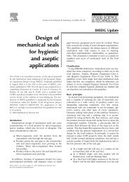
88 Damage scenarios for valves: Identifying the potential for optimisation<br />
supports the switching mechanisms of the disc, so that all<br />
switching operations are performed with minimum stress on<br />
the material.<br />
Extensive tests on the capability of the valve design to<br />
withstand pressure chock (or water hammer) also provide<br />
precise data on the production conditions under which the<br />
valves can be operated. Thus, in the event of unexpected<br />
water hammers (which cannot be entirely ruled out in any<br />
production operation), a clear statement can be made on the<br />
state of the seal. (Figure 4).<br />
Figure 6. Sealing configuration at the valve plate.<br />
In the event of damage to the valve disc, safe and<br />
contamination-free operation of the production line can only<br />
be restored by a time-consuming and expensive replacement<br />
of the valve plate.<br />
The frequently observed phenomenon of the seat seal’s<br />
tearing out at the opening and closing movements of the<br />
valve discs is manifested with one-piece valve discs, where<br />
installation of the seal is, in most cases, not easy, and in<br />
actual practice is also accompanied by a bit of “helping out”<br />
with the use of grease or washing up liquid.<br />
Figure 4. Seal torn out after a water hammer.<br />
The design of a two-part screwed-together valve disc with a<br />
defined installation space for the seal ensures significantly<br />
more precise installation conditions, and concomitantly,<br />
reliable positioning of the seal. This provides concomitant<br />
gains in terms of reliability against pull out and fluid behind<br />
the seal. Leakage detection according EHEDG is warranted<br />
between the parts of the valve disc. (Figure 7).<br />
Weak point: Valve stem and seat seal<br />
In the case of seat valves, it is not uncommon for traces of<br />
wear at the valve disc and the valve shaft to be responsible for<br />
entraining dirt into the product area and for leaks (Figure 5).<br />
Figure 7. Sealing configuration at the seat.<br />
Similar phenomena can be observed with mix proof valves.<br />
Damage to the radial seal and traces of wear at the valve<br />
disc can be prevented by providing a defined installation<br />
space for the seal, and by designing the seal with a support<br />
ring (Figure 8).<br />
Figure 5. Traces of wear on the valve disc.<br />
This is prevented by integrating a second shaft seal, which<br />
strips off any dirt, and avoids any damage to the valve shaft<br />
from wear traces. Leakage detection according EHEDG is<br />
warranted between housing and seat ring. (Figure 6)