

1. magnetic confinement - ENEA - Fusione
1. magnetic confinement - ENEA - Fusione
1. magnetic confinement - ENEA - Fusione

Create successful ePaper yourself
Turn your PDF publications into a flip-book with our unique Google optimized e-Paper software.
<strong>1.</strong> MAGNETIC CONFINEMENT<br />
13<br />
<strong>1.</strong>1 Tokamak Physics<br />
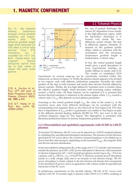
Fig. <strong>1.</strong>4 - Key elements<br />
showing consistency<br />
between critical gradient<br />
modelling and experimental<br />
data. The<br />
effective gradient length<br />
(open dots) saturates (at<br />
≈10) when a critical value<br />
derived from ETG<br />
turbulence (x) is<br />
exceeded (at r=5-7 cm).<br />
Both steady-state and<br />
transient thermal<br />
diffusivity switch from<br />
low to high values at<br />
almost the same radial<br />
position.<br />
[<strong>1.</strong>5] A. Jacchia et al.,<br />
Proc. 14 th AIP Conf. on<br />
Radio Frequency Power in<br />
Plasmas (Oxnard 2001),<br />
Vol. 595, p.342<br />
[<strong>1.</strong>6] G.T. Hoang et al.,<br />
Phys. Rev. Letts 12,<br />
125001 (2001)<br />
R/LT,e<br />
slow<br />
low χ e,hp<br />
#20145(0.140 − 0.160 s)<br />
heat wave<br />
fast<br />
high χ e,hp<br />
R/L T,e -experiment<br />
R/L T,e,crit = 5 + 10 s/q (T.S.)<br />
χ e (p.b.)<br />
χe (m 2 /s)<br />
the case of peaked discharges the<br />
narrow EC deposition occurs mostly<br />
in the high-diffusivity region, while<br />
for flat-hollow discharges it is<br />
located well inside the lowdiffusivity<br />
central volume. The step<br />
in diffusivity appears, therefore, to<br />
depend on the gradient profile<br />
shape, which is consistent with the<br />
assumption that the maximum<br />
temperature gradient length is<br />
limited below a critical value.<br />
In fact, the critical gradient length<br />
model gives a good description of<br />
most experimental findings on<br />
profile stiffness in steady state [<strong>1.</strong>5].<br />
The results of modulated ECH<br />
experiments on current ramp-up can be consistently included within this<br />
framework, as shown in figure <strong>1.</strong>4. Firstly, the plasma column appears to be divided<br />
in two regions, each with different <strong>confinement</strong> properties. Secondly, the radial<br />
position of the step in both transient and steady-state electron thermal diffusivity<br />
almost coincide. Thirdly, the low-high diffusivity transition layer is located where<br />
the effective gradient length, which decreases with increasing radius, stabilises<br />
around a critical value. All these features can be explained if it is assumed that<br />
electron thermal transport is enhanced in the plasma region where 1/L T exceeds a<br />
critical value 1/L T,c that depends on local plasma parameters.<br />
Assuming as the critical gradient length L T,c the value of the actual L T at the<br />
transition layer, data from different discharges can be correlated with the<br />
corresponding local <strong>magnetic</strong> shear, as also observed on Tore Supra [<strong>1.</strong>6]. FTU data<br />
show a dependence of L T,c on the s/q parameter very similar to Tore Supra, in spite<br />
of the different electron heating methods (ECRH for FTU, fast wave in the ion<br />
cyclotron frequency range for Tore Supra). This dependence is consistent with<br />
theoretical predictions based on electron temperature gradient turbulence.<br />
<strong>1.</strong><strong>1.</strong>3 Downshifted and upshifted experiments with ECRH in LHCD<br />
plasmas<br />
To increase CD efficiency, the EC wave can be injected on a LHCD sustained plasma<br />
by exploiting the suprathermal absorption mechanism. The presence of fast electrons<br />
generated by LH waves allows the cyclotron resonant frequency to be shifted up or<br />
down from the cold resonance, depending on the launched N ⎟⎟EC , the <strong>magnetic</strong> field<br />
and the fast electron distribution.<br />
In the downshifted configuration (B T in the range of 6.9 -7.2 T and the cold resonance<br />
outside the plasma), up to 80% of EC power absorption is observed, with increments<br />
in electron temperature (∆T~ 1 keV) and driven plasma current (up to ∆I p ~ 35 kA for<br />
a plasma with I p =350 kA, =0.5×10 20 m -3 ). Electron cyclotron power absorption<br />
results in a loop voltage drop and in an increase in fast electron energy. The EC<br />
power absorption is closely related to the fast electron tail density that corresponds<br />
to the absorbed LH power, and is in agreement with a linear model of suprathermal<br />
interaction of the EC wave.<br />
In preliminary experiments on the up-shift scheme, 700 kW of EC waves were<br />
injected with 30° of toroidal angle in plasma with LHCD (<strong>1.</strong>5–2 MW), resulting in


