

1. magnetic confinement - ENEA - Fusione
1. magnetic confinement - ENEA - Fusione
1. magnetic confinement - ENEA - Fusione

You also want an ePaper? Increase the reach of your titles
YUMPU automatically turns print PDFs into web optimized ePapers that Google loves.
<strong>1.</strong> MAGNETIC CONFINEMENT<br />
29<br />
<strong>1.</strong>2 FTU Facilities<br />
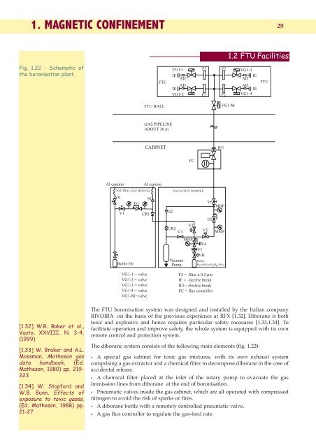
Fig. <strong>1.</strong>22 - Schematic of<br />
the boronisation plant.<br />
FTU<br />
VG1-1<br />
IE<br />
AD<br />
AD<br />
IE<br />
VG1-2<br />
F2<br />
F2<br />
F2<br />
F2<br />
VG1-3<br />
AD<br />
IE<br />
AD<br />
IE<br />
VG1-4<br />
FTU<br />
FTU HALL<br />
VG1-M<br />
GAS PIPELINE<br />
ABOUT 30 m<br />
CABINET<br />
IE1<br />
FC<br />
Al camino<br />
NEUTRAL GAS MODULE<br />
V0<br />
V1<br />
Bottle He<br />
D1<br />
Al camino<br />
S1<br />
CR1<br />
VG1-1 = valve<br />
VG1-2 = valve<br />
VG1-3 = valve<br />
VG1-4 = valve<br />
VG1-M = valve<br />
S2<br />
GAS ACTIVE MODULE<br />
CR2 V3<br />
Vacuum<br />
Pump<br />
V2<br />
MHP<br />
V5<br />
V4<br />
F1<br />
VB<br />
V6<br />
MBP<br />
D2<br />
MMP<br />
Bottle<br />
He (90%)+B 2 H 6 (10%)<br />
F2 = filter a 0.2 µm<br />
IE = electric break<br />
IE1= electric break<br />
FC = flux controller<br />
[<strong>1.</strong>32] W.R. Baker et al.,<br />
Vuoto, XXVIII, N. 3-4,<br />
(1999)<br />
[<strong>1.</strong>33] W. Braker and A.L.<br />
Mossman, Matheson gas<br />
data handbook, (Ed.<br />
Matheson, 1980) pp. 219-<br />
223<br />
[<strong>1.</strong>34] W. Stopford and<br />
W.B. Bunn, Effects of<br />
exposure to toxic gases,<br />
(Ed. Matheson, 1988) pp.<br />
21-27<br />
The FTU boronisation system was designed and installed by the Italian company<br />
RIVOIRA on the basis of the previous experience at RFX [<strong>1.</strong>32]. Diborane is both<br />
toxic and explosive and hence requires particular safety measures [<strong>1.</strong>33,<strong>1.</strong>34]. To<br />
facilitate operation and improve safety, the whole system is equipped with its own<br />
remote control and protection system.<br />
The diborane system consists of the following main elements (fig. <strong>1.</strong>22):<br />
• A special gas cabinet for toxic gas mixtures, with its own exhaust system<br />
comprising a gas extractor and a chemical filter to decompose diborane in the case of<br />
accidental release.<br />
• A chemical filter placed at the inlet of the rotary pump to evacuate the gas<br />
immission lines from diborane at the end of boronisation.<br />
• Pneumatic valves inside the gas cabinet, which are all operated with compressed<br />
nitrogen to avoid the risk of sparks or fires.<br />
• A diborane bottle with a remotely controlled pneumatic valve.<br />
• A gas flux controller to regulate the gas-feed rate.


