

1. magnetic confinement - ENEA - Fusione
1. magnetic confinement - ENEA - Fusione
1. magnetic confinement - ENEA - Fusione

You also want an ePaper? Increase the reach of your titles
YUMPU automatically turns print PDFs into web optimized ePapers that Google loves.
<strong>1.</strong> MAGNETIC CONFINEMENT<br />
31<br />
<strong>1.</strong>2 FTU Facilities<br />
<strong>1.</strong>8<br />
<strong>1.</strong>4<br />
<strong>1.</strong>1<br />
0.7<br />
a)<br />
now complete (six gyrotrons and two coupling<br />
structures). In this configuration, the system has<br />
routinely operated with a total rf power of about 2.2<br />
MW coupled to the plasma. The maximum electron<br />
temperature achieved is about 12 keV. The system has<br />
operated in synergy with the ECRH system, reaching,<br />
in this case, an electron temperature of about 15 keV.<br />
0.4<br />
The new launchers<br />
0.0<br />
0.0<br />
<strong>1.</strong>6<br />
3.2<br />
Fig.<strong>1.</strong>24 a<br />
4.8<br />
1 . 10-3<br />
6.4 8.0<br />
b)<br />
At the end of 2001, the conventional multijunction<br />
(MJ) grill was delivered to <strong>ENEA</strong>. The MJ with passive<br />
waveguides (PAM) and the ancillary components<br />
(dummy loads, short circuits, couplers, etc.) needed<br />
for the complete rf test of both the launchers were still<br />
under construction.<br />
ECRH system<br />
In 2001 the ECRH system operated with two gyrotrons<br />
providing a total power of 800 kW at the plasma, at<br />
nominal pulse length. To improve the power supply<br />
system, a new voltage reference generator was<br />
developed and successfully installed. The new system<br />
is based on National Instruments hardware, has faster<br />
control and a greater rejection of EM noise.<br />
<strong>1.</strong>2.3 Diagnostics<br />
Moments (Nm)<br />
Moments (Nm)<br />
Moments (Nm)<br />
100<br />
0<br />
-100<br />
40<br />
0<br />
-40<br />
-100<br />
-140<br />
0.001<br />
0.002<br />
0.003<br />
0.004<br />
0.005<br />
+ x x x x + + + + + + + + + +<br />
x<br />
+ + +<br />
0.001 x 0.002 0.003<br />
0.004<br />
x x<br />
x<br />
x 0.005<br />
x<br />
x x x<br />
x<br />
x<br />
x<br />
x<br />
x<br />
x<br />
Time (s)<br />
0.006<br />
Time (s)<br />
0.006<br />
40 x x<br />
Time (s)<br />
x<br />
x<br />
0 x x x + + + + + + + + + +<br />
0.001 x 0.002 0.003 0.004 x x 0.006<br />
x<br />
x 0.005<br />
-40<br />
x x x<br />
x<br />
x x<br />
-100<br />
x<br />
x<br />
x<br />
-140<br />
x<br />
x<br />
x<br />
x<br />
+<br />
x<br />
+<br />
x<br />
+<br />
Mx_1<br />
My_1<br />
Mz_1<br />
Mx_2<br />
My_2<br />
Mz_2<br />
Mx_3<br />
My_3<br />
Mz_3<br />
Mx_4<br />
My_4<br />
Mz_4<br />
Mx_5<br />
My_5<br />
Mz_5<br />
Mx_6<br />
My_6<br />
Mz_6<br />
Mx_7<br />
My_7<br />
Mz_7<br />
Mx_8<br />
My_8<br />
Mz_8<br />
Mx_9<br />
My_9<br />
Mz_9<br />
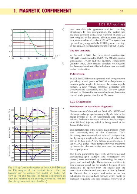
Fig. <strong>1.</strong>24 a) Current disruption at <strong>1.</strong>6 MA. b) FEM used<br />
for EM analysis of the toroidal limiter: tiles are<br />
blanked out to expose the model. c) Radial (x),<br />
vertical (y) and toroidal (z) torque components on<br />
each tile, relative to tile centres, plotted vs. time for<br />
the disruption event described in a).<br />
c)<br />
Development of active beam diagnostics<br />
Measurements of the motional Stark effect (MSE) and<br />
of charge-exchange spectroscopy will yield data on the<br />
radial profiles of q, ion temperature and poloidal<br />
velocity. Both measurements will use a fast-hydrogenatom<br />
(40 keV) injector, which is being tested at the<br />
Frascati laboratory.<br />
The characteristics of the neutral beam injector, which<br />
was previously used in the Canadian TdeV<br />
laboratory, were measured in a reduced configuration,<br />
i.e., by using a single-hole extraction grid rather than<br />
the full 19-hole grid. A new bolometer, consisting of a<br />
set of 12 Cu plates whose temperature was measured<br />
by embedded thermocouples, was used to measure<br />
the output power.<br />
The beam parameters (gas feed, decelerating and<br />
accelerating grid voltages and compressor coil<br />
current) were optimised by maximising the output<br />
power and emitted light. The optimum conditions in<br />
this situation could not be reached because it was<br />
impossible to operate both the source and the<br />
neutraliser at the desired pressures. A directly heated<br />
W filament that is simpler and easier to use has<br />
substituted the original LaB6 cathode, which had to be<br />
replaced frequently and had irregular behaviour. A


