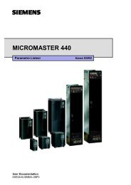
MICROMASTER 440 - Siemens AS
MICROMASTER 440 - Siemens AS
MICROMASTER 440 - Siemens AS

You also want an ePaper? Increase the reach of your titles
YUMPU automatically turns print PDFs into web optimized ePapers that Google loves.
Issue 10/06<br />
6 Commissioning<br />
START<br />
The procedure to manually determine the magnetizing current and to re-calculate<br />
the equivalent circuit diagram data when the drive is operated with closed-loop<br />
vector control (P1300 = 20/21) is shown in the following.<br />
Quick<br />
commissioning<br />
no<br />
Motor data<br />
identification<br />
Operation under<br />
no-load conditions<br />
Criterium<br />
fulfilled <br />
yes<br />
Quick commissioning routine<br />
Using the quick commissioning routine the frequency inverter is adapted to the<br />
motor and important technology parameters are set.<br />
Motor data identification routine<br />
Using the motor data identification routine motor equivalent circuit diagram<br />
data is determined using a measuring technique.<br />
Determining the magnetizing current<br />
In order to determine the magnetizing current (P0320/r0331), the motor should<br />
be accelerated up to approximately 80% of its rated speed under no-load<br />
operating conditions.<br />
In so doing, the following conditions must be carefully maintained:<br />
− the vector control must be activated, P1300 = 20.21<br />
− no field weakening (r0056.8 = 0)<br />
− flux setpoint, r1598 = 100 %<br />
− no efficiency optimization, P1580 = 0 %<br />
No-load operation means that the motor is operated without a load (i.e.<br />
no coupled driven machine).<br />
Under steady-state conditions, a current r0027 is obtained that approximately<br />
corresponds to the rated magnetizing current r0331. (the current is always<br />
less than the no-load current for a pure V/f control).<br />
Measuring and entering the magnetizing current and therefore the associated<br />
new calculation of the equivalent circuit diagram data of the motor is an<br />
iterative procedure. It must be repeated at least 2-3 times until the following<br />
criteria are fulfilled:<br />
− The more accurate the value of the magnetizing current that was<br />
entered, the better the flux setpoint (r1598=100%) matches the flux<br />
actual value (r0084=96..104%) of the observer model.<br />
− The output Xm adaptation (r1787) of the observer model should be<br />
as low as possible. Good values lie between 1-5%. The less that the<br />
Xh adaptation of the observer must operate, the sensitivity of the motor<br />
parameters after power failures are that much less sensitive.<br />
NOTE<br />
In order to display r0084 at the BOP/AOP, the LEVEL 4 parameters must be<br />
enabled using service parameter P3950=46.<br />
P0320 = ...<br />
P0340 = 1<br />
Calculating P0320<br />
Now, the new value can be entered in P0320 from the determined fluxgenerating<br />
current component r0029 by applying the following equation.<br />
P0320 = r0029 * 100 / P0305<br />
Calculating the motor parameters<br />
0<br />
0<br />
The values of the motor equivalent circuit diagram data are calculated from the<br />
entered rating plate data. In addition, the parameters of the controls are pre-set<br />
(subsequently optimized) (P0340 = 3).<br />
END<br />
<strong>MICROM<strong>AS</strong>TER</strong> <strong>440</strong><br />
Operating Instructions (Compact) 33