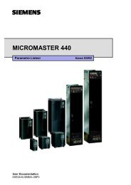
MICROMASTER 440 - Siemens AS
MICROMASTER 440 - Siemens AS
MICROMASTER 440 - Siemens AS

Create successful ePaper yourself
Turn your PDF publications into a flip-book with our unique Google optimized e-Paper software.
Issue 10/06<br />
6 Commissioning<br />
6.4.13 Inverter protection<br />
P0290 = ...<br />
Inverter overload reaction<br />
Selects reaction of inverter to an internal over-temperature.<br />
0 Reduce output frequency<br />
1 Trip (F0004 / F0005)<br />
2 Reduce pulse frequency and output frequency<br />
3 Reduce pulse frequency then trip (F0004)<br />
Inverter monitoring<br />
Inverter overload reaction<br />
P0290<br />
0<br />
r0036<br />
r0037<br />
i 2 t<br />
P0294<br />
Heat sink<br />
temperature<br />
P0292<br />
IGBT<br />
temperature<br />
P0292<br />
i_max control<br />
(U/f)<br />
Current control<br />
(SLVC, VC)<br />
f_pulse<br />
control<br />
A0504<br />
A0505<br />
A0506<br />
F0004<br />
F0005<br />
P0292 =...<br />
Inverter temperature warning<br />
15 °C<br />
Defines the temperature difference (in ºC) between the Overtemperature trip threshold and<br />
the warning threshold of the inverter. The trip threshold is stored internally by the inverter<br />
and cannot be changed by the user.<br />
Temperature warning threshold of inverter T_warn<br />
T = T - P0292<br />
warn<br />
trip<br />
Temperature shutdown threshold of inverter T_trip<br />
Temperature<br />
Heat sink<br />
A - C<br />
110 °C<br />
D - F<br />
95 °C<br />
MM<strong>440</strong>, Frame Size<br />
F<br />
FX<br />
600 V 95 kW 110 kW 132 kW<br />
CT CT CT<br />
80 °C 88 °C 91 °C 80 °C<br />
GX<br />
160 kW<br />
CT<br />
82 °C<br />
200 kW<br />
CT<br />
88 °C<br />
IGBT<br />
140 °C<br />
145 °C<br />
145 °C<br />
150 °C<br />
150 °C<br />
145 °C<br />
147 °C<br />
150 °C<br />
Input rectifier -<br />
-<br />
-<br />
75 °C<br />
75 °C<br />
75 °C<br />
75 °C<br />
75 °C<br />
Cooling air -<br />
-<br />
-<br />
55 °C<br />
55 °C<br />
55 °C<br />
55 °C<br />
50 °C<br />
Control board -<br />
-<br />
-<br />
65 °C 65 °C<br />
65 °C 65 °C<br />
65 °C<br />
P0295 = ...<br />
Delay, fan shutdown<br />
0 s<br />
This defines the delay time in seconds between powering down the frequency inverter and<br />
then powering-down the fan. A setting of 0 means that the fan is immediately shut down<br />
(powered-down).<br />
6.4.14 Motor protection<br />
In addition to the thermal motor protection, the motor temperature is also included<br />
in the adaptation of the motor equivalent circuit diagram data. Especially for a high<br />
thermal motor load, this adaptation has a significant influence on the degree of<br />
stability of the closed-loop vector control. For MM<strong>440</strong> the motor temperature can<br />
only be measured using a KTY84 sensor. For the parameter setting P0601 = 0,1,<br />
the motor temperature is calculated / estimated using the thermal motor model.<br />
If the frequency inverter is permanently supplied with an external 24V voltage, then<br />
the motor temperature is also tracked/corrected using the motor temperature time<br />
constant – even when the line supply voltage is switched-out.<br />
<strong>MICROM<strong>AS</strong>TER</strong> <strong>440</strong><br />
Operating Instructions (Compact) 45