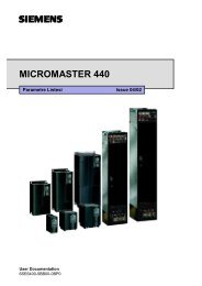
MICROMASTER 440 - Siemens AS
MICROMASTER 440 - Siemens AS
MICROMASTER 440 - Siemens AS

Create successful ePaper yourself
Turn your PDF publications into a flip-book with our unique Google optimized e-Paper software.
6 Commissioning Issue 10/06<br />
6.4.20 Diagnostic parameters<br />
r0021<br />
r0022<br />
r0032<br />
CO: Act. filtered frequency<br />
Displays actual inverter output frequency (r0021) excluding slip compensation, resonance<br />
damping and frequency limitation.<br />
Act. filtered rotor speed<br />
Displays calculated rotor speed based on inverter output frequency [Hz] x 120 / number of<br />
poles.<br />
r0022 [1/min]<br />
= r0021[Hz] ⋅<br />
60<br />
r0313<br />
CO: Act. filtered power<br />
Displays motor power (power output at the motor shaft).<br />
Motor<br />
ω, M<br />
Pmech = ω ⋅M<br />
= 2 ⋅ π ⋅ f ⋅M<br />
⇒<br />
1<br />
r0032 [kW] =<br />
1000<br />
⋅ 2 ⋅ π ⋅<br />
r0022<br />
60<br />
[1/min] ⋅ r0031[Nm]<br />
r0032 [hp] = 0.75 ⋅ r0032 [kW]<br />
r0035<br />
r0036<br />
r0039<br />
CO: Motor temperature<br />
Displays the measured motor temperature in °C.<br />
CO: Frequency inverter utilization<br />
Displays the frequency inverter utilization as a % referred to the overload. In so doing, the<br />
value is calculated using the I 2 t model.<br />
The I 2 t actual value relative to the maximum possible I 2 t value provides the level of<br />
utilization.<br />
CO: Energy consumpt. meter [kWh]<br />
Displays electrical energy used by inverter since display was last reset.<br />
tist<br />
tist<br />
r0039 = ∫PW<br />
⋅ dt = ∫<br />
0<br />
0<br />
3 ⋅ u ⋅ i ⋅ cos ϕ ⋅ dt<br />
r0052 CO/BO: Act. status word 1<br />
Displays the first active status word (ZSW) of the frequency inverter (bit format) and can be<br />
used to diagnose the inverter status.<br />
Bit00 Drive ready 0 NO 1 YES<br />
Bit01 Drive ready to run 0 NO 1 YES<br />
Bit02 Drive running 0 NO 1 YES<br />
Bit03 Drive fault active 0 NO 1 YES<br />
Bit04 OFF2 active 0 YES 1 NO<br />
Bit05 OFF3 active 0 YES 1 NO<br />
Bit06 ON inhibit active 0 NO 1 YES<br />
Bit07 Drive warning active 0 NO 1 YES<br />
Bit08 Deviation setpoint / act. value 0 YES 1 NO<br />
Bit09 PZD control 0 NO 1 YES<br />
Bit10 Maximum frequency reached 0 NO 1 YES<br />
Bit11 Warning: Motor current limit 0 YES 1 NO<br />
Bit12 Motor holding brake active 0 NO 1 YES<br />
Bit13 Motor overload 0 YES 1 NO<br />
Bit14 Motor runs right 0 NO 1 YES<br />
Bit15 Inverter overload 0 YES 1 NO<br />
<strong>MICROM<strong>AS</strong>TER</strong> <strong>440</strong><br />
72 Operating Instructions (Compact)