

Radio Broadcast - 1925, February - 113 Pages ... - VacuumTubeEra
Radio Broadcast - 1925, February - 113 Pages ... - VacuumTubeEra
Radio Broadcast - 1925, February - 113 Pages ... - VacuumTubeEra

Create successful ePaper yourself
Turn your PDF publications into a flip-book with our unique Google optimized e-Paper software.
What Reflex<br />
Means<br />
How One Tube is Made to Do the Work of Two Problems of Reflexing and<br />
How They Are Solved Various Uses of Reflexing Another Family Tree Diagram<br />
BY JULIAN KAY<br />
TH IS article in this series of informative articles about some of the technical phases<br />
of radio written in a decidedly non-technical fashion deals this month with the use<br />
of reflexing. The patent on the reflex system dates back to <strong>February</strong>, 1913, when<br />
Schloemilch and Van Bronck had their application approved. There are few who<br />
have heard something about radio who haven't also heard the word "reflex."<br />
Many radio listeners want a good review of reflexing and that is just what Mr.<br />
Kay has done. Other articles in Mr. Kay's "What's In a Name" series have<br />
discussed the various classes of receivers in use, radio-frequency amplification, audiofrequency<br />
amplification, and the super-heterodyne. THE EDITOR.<br />
THE<br />
old song that "every little bit<br />
added to what you've got makes just<br />
a little bit more" applies nowhere<br />
in radio quite so well as in this reflex<br />
business. Given a small pocket book and a<br />
long way to go via radio, what is one to do<br />
The answer is to add just the little bit more<br />
and that is what reflexing effectually does.<br />
In the preceeding articles of this series, the<br />
various forms of detectors and amplifiers havebeen<br />
analyzed as separate units. Some mention<br />
has been .made* of complete receiving<br />
equipment such as the neutrodyne and the<br />
heterodyne, both of which are really efficient<br />
combinations both of detectors and amplifiers.<br />
It is in the latter class of complete receivers<br />
that the reflex lies.<br />
The Family Tree diagram on page 672 shows<br />
the place of the reflex among radio circuits.<br />
It is a combination, a sort of trick combination<br />
if<br />
you will, of a detector and two amplifiers.<br />
The reflex idea may be extended to other complete<br />
receiving systems, such as to the neutrodyne,<br />
for example in the Fada 160, or to the<br />
super-heterodyne as in the <strong>Radio</strong>la.<br />
The main idea of reflexing is to do away with<br />
one vacuum tube, to make one do the work of<br />
two. And while it is fairly simple to build a<br />
detector and an amplifier as separate units,<br />
it is a more difficult problem to build a reflex<br />
that works as well as the more complicated<br />
apparatus it replaces. Unless the reflex is<br />
correctly constructed from tried and true<br />
methods it will lose as much or more than it<br />
gains a state of affairs that is not true economy.<br />
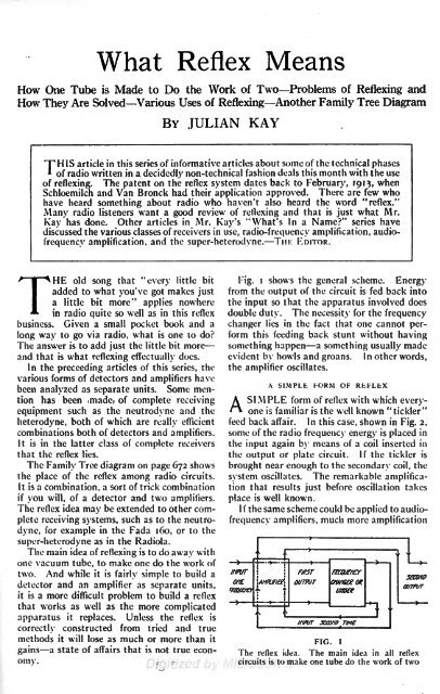
Fig. shows the i general scheme. Energy<br />
from the output of the circuit is fed back into<br />
the input so that the apparatus involved does<br />
double duty. The necessity for the frequency<br />
changer lies in the fact that one cannot perform<br />
this feeding back stunt without having<br />
something happen a something usually made<br />
evident by howls and groans. In other words,<br />
the amplifier oscillates.<br />
A SIMPLE FORM OF REFLEX<br />
A SIMPLE form of reflex with which everyone<br />
is familiar is the well known "tickler"<br />
feed back affair. In this case, shown in Fig. 2,<br />
some of the radio frequency energy is placed in<br />
the input again by means of a coil inserted in<br />
the output or plate circuit. If the tickler is<br />
brought near enough to the secondary coil, the<br />
system oscillates. The remarkable amplification<br />
that results just before oscillation takes<br />
place is well known.<br />
I f the same scheme could be applied to audiofrequency<br />
amplifiers, much more amplification<br />
INPUT


