

Radio Broadcast - 1925, February - 113 Pages ... - VacuumTubeEra
Radio Broadcast - 1925, February - 113 Pages ... - VacuumTubeEra
Radio Broadcast - 1925, February - 113 Pages ... - VacuumTubeEra

Create successful ePaper yourself
Turn your PDF publications into a flip-book with our unique Google optimized e-Paper software.
Problems of Receiver Design 743<br />
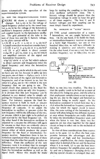
shows schematically the operation<br />
super-heterodyne system.<br />
of the<br />
79.<br />
HOW THE FREQUENCY-CHANGER WORKS<br />
FIGURE 66 shows a typical frequency<br />
changer. Let e s sin st be the voltage of<br />
signal frequency picked up by the tuned loop.<br />
Let e h sin ht be the voltage of the heterodyne<br />
oscillator's frequency picked up by the small<br />
coil coupled loosely to the heterodyne oscillator.<br />
The grid potential of the tube is the<br />
sum of these two and the C battery voltage,<br />
so the plate current will be<br />
= K<br />
i,, [B + n (C + e s sin st + e h sin ht)|-<br />
+ (small terms that we need not consider here.)<br />
2<br />
= K [(B + M C) + /* (es sin st + e h sin ht)]<br />
= K (B + jLtC) 2 which is direct current<br />
-f-2k/x (B + /xC) (es sinst -f- e h sin ht) which<br />
are amplified currents of the signal and<br />
heterodyne frequencies.<br />
-<br />
+ k/z- (es sin' 2 st -f e h 2 sin -ht) which reduces<br />
to direct currents and frequencies twice the<br />
signal frequency and twice the heterodyne<br />
frequency.<br />
+2kju 2 e s sin st Ch sin ht which is the only term<br />
we have any use for, because it splits up into<br />
two parts, one of them Kju 2 e s e h cos (s + h ) t<br />
which is the sum of the signal and heterodyne<br />
frequencies, and of no interest to us, but the<br />
other is k n-esQh cos (s h) t which is the new<br />
frequency that we are going to use. The<br />
tuned circuit that connects to the fixed frequency<br />
receiver picks up only this frequency.<br />
It is obvious that this new frequency can be<br />
adjusted to any desired value by simply adjusting<br />
the frequency of the heterodyne oscillator.<br />
For instance, suppose the fixed frequency<br />
receiver is built to work at 100,000<br />
cycles and the radio waves are coming in at a<br />
frequency of 1,000,000. If we adjust the<br />
heterodyne to oscillate at 900,000 cycles the<br />
new frequency will be the difference of the two,<br />
or 100,000, which is just right to be picked up<br />
and received by the fixed frequency set. On<br />
the other hand if the heterodyne oscillator is<br />
adjusted to 1,100,000 the difference will again<br />
be 100,000 so that there are evidently always<br />
two possible settings for the heterodyne condenser<br />
either of which produces the proper<br />
frequency for the fixed or intermediate frequency<br />
receiver. Sometimes there is less interference<br />
experienced when using one of these<br />
settings than the other but usually<br />
it makes no<br />
difference. From the coefficient of the new<br />
frequency term it is evident that its strength<br />
depends upon the amount of voltage picked up<br />
from the heterodyne oscillator as well as the<br />
signal itself. Hence this should be made<br />
large by making the coupling to the heterodyne<br />
oscillator sufficiently close. The C<br />
battery voltage should be greater than the<br />
heterodyne voltage in order to keep the grid<br />
at all times negative. The best C and B<br />
battery voltages and best coupling can be<br />
most simply found by experiment.<br />
80. PROBLEMS OF "SUPER" DESIGN<br />
IN THE actual construction of a superheterodyne,<br />
we are caught between two<br />
fires. On the one hand, if we build the fixed,<br />
or intermediate-frequency receiver to operate<br />
at a fairly high frequency, say one or two<br />
hundred kilocycles, we will have difficulty in<br />
making it sensitive and selective enough.<br />
On the other hand, if we use a very low intermediate<br />
frequency, say 30 kilocycles, we are<br />
TO HETERODYNE<br />
OSCILLATOR<br />
-L.<br />
TO FIXED FREQUENCf<br />
RECEIVING bT-<br />
THESE TWO TUNED CIRCUITS TAKE THE<br />
PLACE OF THE BAND FILTER WELL ENOUGH<br />
FOR MOST PURPOSES<br />
FIG. 66<br />
likely to run into two troubles. The first is<br />
that the quality tends to be bad on account of<br />
the selectivity being too great, and the other is<br />
that unpleasant complications occur in operating<br />
the set, due to the signal and heterodyne<br />
frequencies being so nearly equal. As the<br />
heterodyne condenser is varied there may be a<br />
click when the heterodyne frequency passes the<br />
value for which the signal circuit is tuned.<br />
Also, the same setting of the heterodyne condenser<br />
will often bring in two different stations<br />
at once whose frequencies are really<br />
different<br />
by twice the intermediate frequency used, and<br />
when the latter is<br />
very low, these two frequencies<br />
are too close together for the signal<br />
circuit or loop to select one to the exclusion of<br />
the other.<br />
In view of these considerations three courses<br />
seem to be open: (i) to effect the best compromise<br />
between the advantages and disadvantages<br />
of high and low intermediatefrequency<br />
amplification, the choice depending<br />
upon what is desired of the set and the location<br />
where it is to work, (2) to use the best intermediate<br />
frequency for amplification and quality<br />
and use a frequency changing device employing<br />
special circuits so arranged that only


