

Radio Broadcast - 1925, February - 113 Pages ... - VacuumTubeEra
Radio Broadcast - 1925, February - 113 Pages ... - VacuumTubeEra
Radio Broadcast - 1925, February - 113 Pages ... - VacuumTubeEra

Create successful ePaper yourself
Turn your PDF publications into a flip-book with our unique Google optimized e-Paper software.
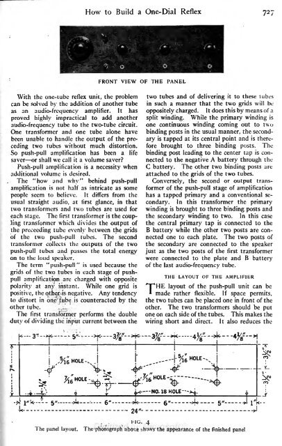
How to Build a One-Dial Reflex 727<br />
FRONT VIEW OF THE<br />
PANEL<br />
With the one-tube reflex unit, the problem<br />
can be solved by the addition of another tube<br />
as an audio-frequency amplifier. It has<br />
proved highly impractical to add another<br />
tube to the two-tube circuit.<br />
audio-frequency<br />
One transformer and one tube alone have<br />
been unable to handle the output of the preceding<br />
two tubes without much distortion.<br />
So push-pull amplification has been a life<br />
saver or shall we call it a volume saver<br />
Push-pull amplification is a necessity when<br />
additional volume is desired.<br />
The "how and why" behind push-pull<br />
amplification<br />
is not half as intricate as some<br />
people seem to believe. It differs from the<br />
usual straight audio, at first glance, in that<br />
two transformers and two tubes are used for<br />
each stage. The first transformer is the coupling<br />
transformer which divides the output of<br />
the prccecding tube evenly between the grids<br />
of the two push-pull tubes. The second<br />
transformer collects the outputs of the two<br />
push-pull tubes and passes the total energy<br />
on to the loud speaker.<br />
The term "push-pull"<br />
is used because the<br />
grids of the two tubes in each stage of pushpull<br />
amplification are charged with opposite<br />
polarity at any instant. While one grid is<br />
positive, the other is negative. Any tendency<br />
to distort in one tube is counteracted by the<br />
other tube.<br />
The first transformer performs the double<br />
duty of dividing the input current between the<br />
two tubes and of delivering<br />
it to these tubes<br />
in such a manner that the two grids will be<br />
oppositely charged.<br />
It does this by means of a<br />
split winding. While the primary winding is<br />
one continuous winding coming out to two<br />
binding posts in the usual manner, the secondary<br />
is tapped at its central point and is therefore<br />
brought to three binding posts. The<br />
binding post leading to the center tap is connected<br />
to the negative A battery through the<br />
C battery. The other two binding posts are<br />
attached to the grids of the two tubes.<br />
Conversely, the second or output transformer<br />
of the push-pull stage of amplification<br />
has a tapped primary and a conventional secondary.<br />
In this transformer the primary<br />
winding is brought to three binding posts and<br />
the secondary winding to two. In this case<br />
the central primary tap<br />
is connected to the<br />
B battery while the other two posts are connected<br />
one to each plate. The two posts of<br />
the secondary are connected to the speaker<br />
just as the two posts of the first transformer<br />
were connected to the plate and B battery<br />
of the last audio-frequency tube.<br />
THE LAYOUT OF THE AMPLIFIER<br />
THE layout of the push-pull unit can be<br />
made rather flexible. If space permits,<br />
the two tubes can be placed one in front of the<br />
other. The two transformers should be put<br />
one on each side of the tubes. This makes the<br />
wiring short and direct. It also reduces the<br />
[j<<br />
-5"<br />
>j< -3^--H<<br />
-<br />
3%-"-->K 4


