

Radio Broadcast - 1925, February - 113 Pages ... - VacuumTubeEra
Radio Broadcast - 1925, February - 113 Pages ... - VacuumTubeEra
Radio Broadcast - 1925, February - 113 Pages ... - VacuumTubeEra

Create successful ePaper yourself
Turn your PDF publications into a flip-book with our unique Google optimized e-Paper software.
A Winder for<br />
Small Inductances<br />
How to Build and Use a Device to Wind Efficient, Concentrated Inductances<br />
Which May be Used in Various <strong>Radio</strong> Receivers How to Wind the Coils<br />
for the RADIO BROADCAST Six-Tube Second Harmonic Super-heterodyne<br />
BY ALLAN T.<br />
HANSCOM<br />
\AANY readers have been greatly interested in the second harmonic super-<br />
* *<br />
heterodyne described in RADIO BROADCAST for November, 1924. One of<br />
the central features of that six-tube receiver is the concentrated inductances.<br />
These are wound by a special machine which is described here. The construction<br />
of this device is not especially easy and had best be assumed by those readers<br />
who are adept at using a lathe and similar tools. In addition to the method<br />
of assembling the winder, complete information is given on the number of turns<br />
and dimensions for the intermediate frequency and oscillator coils for the sixtube,<br />
second harmonic super-heterodyne. THE EDITOR.<br />
O MANY requests have come to the<br />
writer for constructional data on the<br />
"sjnall<br />
honeycomb coils which are used<br />
in the six-tube super-heterodyne discribed<br />
in this magazine for November, 1924,<br />
that a description of the method by which<br />
these coils are made should prove interesting.<br />
In the first place, some of the more important<br />
requirements for any inductance to be<br />
used in radio work should be considered.<br />
LOW DISTRIBUTED CAPACITY<br />
p\ISTRIBUTED capacity in an inductance<br />
1' greatly increases the resistance of the<br />
inductance at the higher frequencies. The<br />
direct current resistance of an inductance is<br />
an inverse function of the wire size. By this<br />
we mean that the resistance of a coil of coarse<br />
wire is less than a similar coil of fine wire, but<br />
with coarse wire the distributed capacity in-<br />
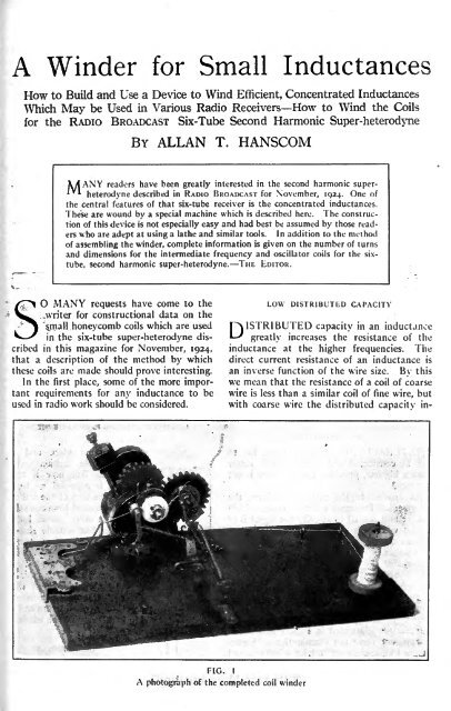
FIG. I<br />
A photograph of the completed coi! winder


