

Radio Broadcast - 1925, February - 113 Pages ... - VacuumTubeEra
Radio Broadcast - 1925, February - 113 Pages ... - VacuumTubeEra
Radio Broadcast - 1925, February - 113 Pages ... - VacuumTubeEra

Create successful ePaper yourself
Turn your PDF publications into a flip-book with our unique Google optimized e-Paper software.
:<br />
crystal<br />
!<br />
toward<br />
: this<br />
What Reflex Means 675<br />
iripur<br />
OUTPUT<br />
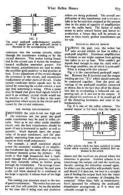
FIG. 7<br />
The usual push-pull audio-frequency amplifier<br />
circuit. A special case of the push-pull circuit is<br />
discussed in the accompanying article<br />
resistance into the various circuits, either<br />
through the transformer winding or by the<br />
detector. This makes tuning broad,<br />
and in the crystal case it makes the tendency<br />
oscillation somewhat greater. For<br />
reason, potentiometers are used to make<br />
the amplifier grids positive a bad practice at<br />
best. Every adjustment of the crystal changes<br />
the resistance in the circuit, and necessitates<br />
readjustment of other parts of the set. Under<br />
certain conditions better signals may be obtained<br />
by removing the crystal contact, a sure<br />
3ign that something is wrong. Often a point<br />
may be found that gives loud signals which if<br />
used in an ordinary crystal circuit would not<br />
be sensitive at all. This is due to the semiregeneration<br />
which occurs in the circuit and is<br />
caused by the crystal resistance.<br />
THE PROPER TRANSFORMERS<br />
OROVIDED the ratio is not too high and<br />
\ the resistance not too great, any good<br />
audio transformer may be used in reflex circuits.<br />
Here as in any other audio amplifier<br />
circuit, only the best transformers should be<br />
used if one is interested in quality as well as<br />
quantity. Much depends upon the proper<br />
value of by-pass condensers, and the poor<br />
quality emanating from some reflexes may be<br />
traced to these small components.<br />
For example, a small condenser placed<br />
across the secondary winding of an amplifying<br />
transformer has the same effect as a large<br />
condenser shunted across the primary. The<br />
result is that high frequencies find a ready<br />
path through this effective primary capacity,<br />
and they naturally refuse to bother going<br />
through the transformer. The average transformer<br />
is a poor device anyway beyond 3000<br />
cycles and when shunted by a condenser of<br />
too large a capacity it misses most of the high<br />
notes.<br />
The coming year promises much in the way<br />
of good transformers. The writer has seen one<br />
new coil that will probably be on the market<br />
by the time this is<br />
being read and doubtless<br />
others are being perfected. The overall amplification<br />
of this transformer and a uv-2oi-A<br />
tube is far beyond that attained at the present<br />
time in the point of equality of amplification<br />
over the audio band. The future of radio<br />
seems to point toward better and better reproduction,<br />
a future that will be present as<br />
soon as more nearly perfect transformers are<br />
for sale.<br />
PUSH-PULL REFLEX HOKUM<br />
POURING the past year, the writer has<br />
I' seen several articles on how to reflex a<br />
push-pull amplifier. Enormous amplification<br />
is claimed, as one might suppose from getting<br />
two tubes to act as four. Who couldn't get<br />
signals loud enough to stop the clock with a<br />
four stage amplifier, one of which is<br />
push-pull<br />
What is<br />
wrong with this scheme<br />
Fig. 7 is the conventional push-pull amplifier.<br />
Between the B batteries and the output<br />
winding are two "XV which should normally<br />
be connected together. Now the great advantage<br />
of the push-pull amplifier connected<br />
as shown, lies in the fact that all of the distortion<br />
due to overloading is balanced out, appearing<br />
only at X and not in the output. 'Jf<br />
one placed his receivers at X he would get all<br />
of the distorting harmonics and none of the<br />
fundamentals.<br />
Fig. 8 is one of the reflex schemes. The<br />
normal output is fed back into the input as<br />
IfiPUT<br />
FIG. 8<br />
A reflex scheme which has been exploited to some<br />
extent which contains a serious technical flaw explained<br />
in the article<br />
shown and the receivers are placed where the<br />
distortion is greatest. Another scheme is to<br />
interchange the output coil and the receivers,<br />
thereby sending the distortion around again.<br />
In either case the amplifier will probably howl,<br />
and should if it does not, for here is a straight<br />
case of feeding the output back into the input<br />
without the usual ceremony of changing frequencies!<br />
Other ideas, fully as unnecessary,<br />
haveTappeared for reflexing the push-pull,<br />
transformer arrangement as if it were not<br />
valuable enough by itself.


