

Radio Broadcast - 1925, February - 113 Pages ... - VacuumTubeEra
Radio Broadcast - 1925, February - 113 Pages ... - VacuumTubeEra
Radio Broadcast - 1925, February - 113 Pages ... - VacuumTubeEra

Create successful ePaper yourself
Turn your PDF publications into a flip-book with our unique Google optimized e-Paper software.
What Reflex Means 673<br />
might be expected. Here, however, we are<br />
dealing with a different problem. In the tickler<br />
case we are interested in a very small percentage<br />
of the total frequency, that of the incoming<br />
signals, say one million cycles. The<br />
tuning is so adjusted and the position of the<br />
FIG. 2<br />
One of the simplest forms of reflex and one of the<br />
best known. The coil in the plate circuit is known<br />
to all users of regenerative sets. Some of the radio<br />
frequency energy is fed back again through the tickler<br />
coil to the primary circuit<br />
tickler so arranged that oscillations over this<br />
comparatively narrow band can be controlled.<br />
In audio-frequency amplifiers, however, we<br />
are interested in the uniform amplification of<br />
the whole band of frequencies from fifty to<br />
several thousand cycles. If the tickler were<br />
adjusted for one particular frequency, oscillations<br />
would probably occur at another. For<br />
code reception where all signals can be brought<br />
to a single audible note, say 1000 cycles, the<br />
audio amplifier may be made to regenerate in<br />
this fashion with remarkable results.<br />
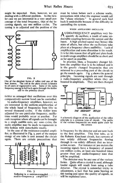
In the case of the resistance-coupled amplifier,<br />
as illustrated in Fig. 3, part of the output<br />
energy of one tube is sent around the circuit<br />
again. There are certain precautions that<br />
must be taken before such a scheme works,<br />
precautions with what the engineer would call<br />
the "phase relations." In general such feed<br />
back is undesirable because of the difficulty in<br />
controlling the system.<br />
WHEN AMPLIFIERS OSCILLATE<br />
A UDIO-FREQUENCY amplifiers very<br />
** fre-<br />
quently do oscillate, a result of some undesirable<br />
coupling between the output and the<br />
A high pitched squeal may betray this<br />
input.<br />
state of affairs, but often the oscillations take<br />
place at a frequency above audibility. Lack of<br />
amplification and some distortion is the result.<br />
It is for this reason that all grid and plate leads<br />
in multi-stage amplifiers should be as short and<br />
as far apart as possible.<br />
In practice, then, a frequency changer follows<br />
the amplifier that is to be reflexed and it<br />
is the greatly changed frequencies that are<br />
returned to a precceding part of the circuit to<br />
go the rounds again. Fig. 4 shows the general<br />
principle. Incoming signals are sent through<br />
a radio-frequency amplifier where they are<br />
boosted in amplitude. They are then changed<br />
ITAfflO(<br />
tKKtUOK)<br />
r


