

Radio Broadcast - 1925, February - 113 Pages ... - VacuumTubeEra
Radio Broadcast - 1925, February - 113 Pages ... - VacuumTubeEra
Radio Broadcast - 1925, February - 113 Pages ... - VacuumTubeEra

You also want an ePaper? Increase the reach of your titles
YUMPU automatically turns print PDFs into web optimized ePapers that Google loves.
<strong>Radio</strong><br />
<strong>Broadcast</strong><br />
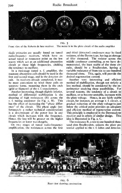
Front view of the Roberts de luxe receiver.<br />
FIG. 5<br />
The meter is in the plate circuit of the audio amplifier<br />
riodic primaries arc usually found on tuned<br />
radio-frequency receivers, which have an<br />
actual tuned or resonance point on the low<br />
wa,ves which act as an additional absorption<br />
circuit at these high frequencies, choking<br />
the tendency to oscillate.<br />
In a two-stage tuned r. f. amplifier, the<br />
resonant absorption coils should be used in the<br />
first and second stage, and in the detector circuit.<br />
In receivers already completed, it may<br />
be most convenient to wind these coils on<br />
separate forms, mounting them in the ends<br />
(grid or filament) of the r. f. transformers.<br />
Another interesting, though slightly inferior,<br />
method of differential stabilization is the<br />
shunting of high resistances (R) across the<br />
r. f.<br />
tuning condenser (in Fig. 2, B). This<br />
has the effect of increasing the "phase difference"<br />
of the circuit. The phase angle (unfortunately<br />
a rather technical consideration)<br />
is a determinant of the power loss in any<br />
circuit which increases with the frequency.<br />
Hence, the loss will be greater on the higher<br />
frequencies or lower wavelengths.<br />
On two stages of tuned radio-frequency<br />
amplification, the resistances across the first<br />
and third (detector) condensers may be fixed<br />
resistors, of the Daven type, having an ohmage<br />
of fifty thousand. The resistor across the<br />
middle condenser controlling, as we have demonstrated,<br />
the least<br />
stable of the three circuits,<br />
should be a Bradleyohm, having a<br />
variable resistance of from ten to one hundred<br />
thousand ohms. This, again, will provide the<br />
desired regeneration control.<br />
Another very interesting and efficient<br />
method of stabilization, though not strictly a<br />
loss method, should be considered by the experimenter<br />
studying these possibilities. For<br />
several reasons, the tendency of a circuit to<br />
oscillate, or to become unstable, increases with<br />
the plate voltage. Hence, in any fairly stable<br />
circuit, for instance, an average r. f. circuit, a<br />
gradual reduction of the plate voltage to just<br />
below the critical point provides an adequate<br />
and efficient method of regeneration control.<br />
This principle is<br />
employed in the Deresnadyne<br />
receiver and in others of similar design. This<br />
idea is illustrated in Fig. 2, C.<br />
The resistance R, a ten to one hundred thousand<br />
ohm Bradleyohm, adjusts the plate potential<br />
applied to the r. f. tubes and detector.<br />
FIG. 6<br />
Rear view showing construction


