

Radio Broadcast - 1925, February - 113 Pages ... - VacuumTubeEra
Radio Broadcast - 1925, February - 113 Pages ... - VacuumTubeEra
Radio Broadcast - 1925, February - 113 Pages ... - VacuumTubeEra

You also want an ePaper? Increase the reach of your titles
YUMPU automatically turns print PDFs into web optimized ePapers that Google loves.
724<br />
<strong>Radio</strong> <strong>Broadcast</strong><br />
.0005 OPTIONAL<br />
HI-<br />
FIG.<br />
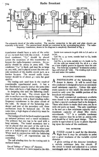
The schematic circuit of the reflex receiver. The peculiar connection to the grid and plate circuits are<br />
especially to be noted. The constructional details are contained in the accompanying article. The radiofrequency<br />
transformer, shown in the diagram is completely illustrated in Fig. 3<br />
I<br />
transformer should have a ratio of the order<br />
of 10:1 to work best with the crystal. A small<br />
fixed condenser, "3" should be placed<br />
across the secondary of this transformer to<br />
bypass the radio-frequency currents. Its capacity<br />
should be .00025 or .0005 mfd. The<br />
condenser "4"<br />
is fixed, and may be as large<br />
as .005 mfd., and is<br />
placed across the two outside<br />
terminals of the double circuit jack, as a<br />
further by-pass. The second audio transformer<br />
should be of about 4:1 ratio for good<br />
quality.<br />
The tuning unit used here is the result of<br />
considerable experimental work. It has a<br />
low distributed capacity and at the same time<br />
the three coils have a high degree of coupling.<br />
In designing this unit the following conditions<br />
had to be met. The circuit must be<br />
able to oscillate over the entire range of broadcast<br />
wavelengths, with a fixed winding radiofrequency<br />
transformer in the plate circuit of<br />
the tube. By means of the balancing condenser<br />
and part of the secondary coil, these<br />
oscillations must be balanced out. At the<br />
same time, a high degree of selectivity must be<br />
maintained.<br />
Thetuningcoilisofthefixedcouplertypewith<br />
an untuned primary and a tuned secondary.<br />
The primary has one tap to be used with a<br />
long antenna. The tuned secondary has a<br />
tap so placed that one part of the coil is included<br />
in the grid circuit, while the other part<br />
acts as a balancing-out or compensating<br />
When coil.<br />
used in conjunction with the balancing<br />
condenser "CB", all regeneration can be<br />
controlled.<br />
The coil winding data for the tuning unit is<br />
outlined below:<br />
Size of Tubing:--2" long x if" diameter.<br />
Coil No. i consists of 21 turns tapped at the i6th.<br />
Inside turn connects to grid i6th to LA and 21 st<br />
to SA.<br />
Coil No. 2, 35 turns, outside lead to C2, inside<br />
lead to A.<br />
Coil No. 5, 25 turns, outside to A, inside to Cl.<br />
All the coils are wound with No. 26 d. s. c. wire<br />
on a form slightly greater in diameter than the tubing.<br />
The form has 19 spokes f" in diameter producing<br />
a coil about iV wide. The winding style is over<br />
two and under two spokes.<br />
BALANCING CONDENSER<br />
A PHOTOGRAPH of the balancing condenser<br />
is shown. It will be noted that<br />
this condenser is<br />
designed to have an extremely<br />
small minimum capacity. Unless this minimum<br />
capacity is very small, the circuit will be<br />
of the<br />
sensitive only over the middle portion<br />
broadcast wavelengths.<br />
The small commercial condensers available<br />
were found to be unsuitable for this purpose,<br />
so that a special condenser had to be designed.<br />
Those who desire to make their own can do so<br />
with old parts on hand. The only conditions<br />
to be met are a low minimum capacity and a<br />
maximum capacity of about fifty micromicrofarads.<br />
"C" is a variable condenser<br />
whose capacity may be as low as .00029 mfd.<br />
and should be of fairly good design. This capacity<br />
is equivalent to 13 to 17 plates depending<br />
upon the make of the condenser.<br />
A FIXED crystal<br />
THE DETECTOR<br />
is used for the detector.<br />
Right here it may be advisable to point<br />
out a great weakness of the variable crystal<br />
detector.<br />
A given setting of the detector introduces<br />
a certain resistance into the circuit. If<br />
the circuit is tuned and adjusted to a certain<br />
wavelength and the variable detector is then


