Radio Broadcast - 1925, February - 113 Pages ... - VacuumTubeEra
Radio Broadcast - 1925, February - 113 Pages ... - VacuumTubeEra
Radio Broadcast - 1925, February - 113 Pages ... - VacuumTubeEra
You also want an ePaper? Increase the reach of your titles
YUMPU automatically turns print PDFs into web optimized ePapers that Google loves.
How to Build a One-Dial Reflex 729<br />
enough to light the filament<br />
or the tube will be burned<br />
out<br />
Ȧ negative C battery<br />
is used<br />
to cut down the B battery<br />
consumption and to improve<br />
the quality of signals through<br />
preventing distortion.<br />
To operate at its best efficiency,<br />
the set should oscillate<br />
or be very near the oscillating<br />
point over the entire range of<br />
broadcasting wavelengths,<br />
when the balancing condenser<br />
is at- its minimum. At this<br />
point the dial controlling this<br />
condenser should read 100 degrees.<br />
When this dial reads<br />
near zero, oscillations should<br />
not occur at any wavelength.<br />
TUNING<br />
THE method of tuning this<br />
set is<br />
very simple and can<br />
be mastered in a few minutes.<br />
It will be observed that the large dial at the<br />
left is labelled "Tuning." The next dial to<br />
the right is labelled "Volume." To the right<br />
of the dial controlling volume are three rheostat<br />
knobs, which control the current in the<br />
filaments of the first, second, third, and fourth<br />
tubes. Immediately below the volume control<br />
dial is the filament current control switch.<br />
Continuing to the right of this switch and<br />
below the first rheostat knob is a jack for use<br />
of phones with only one stage of amplification.<br />
Then there is a second jack for the speaker,<br />
using both stages of amplification and the last<br />
jack employs all four tubes.<br />
At first it will probably be best to try to<br />
tune the set with powerful near-by stations.<br />
To do this you set the volume control dial<br />
near zero and slowly rotate the tuning dial.<br />
Then having picked up a local station, by<br />
increasing the reading of the volume control<br />
dial, the signal should come in loud and clear.<br />
The setting of the tuning dial should be recorded<br />
and thereafter that particular station<br />
should always be found at that setting.<br />
To obtain maximum volume on distant<br />
station reception the procedure is slightly<br />
different. In this case it is best to set the<br />
tuning dial approximately at the desired<br />
wavelength and for each of these settings increase<br />
the volume control dial until you get<br />
a hissing noise. If you go beyond this point<br />
you will get an audio note and the volume<br />
dial setting should be reduced. Generally<br />
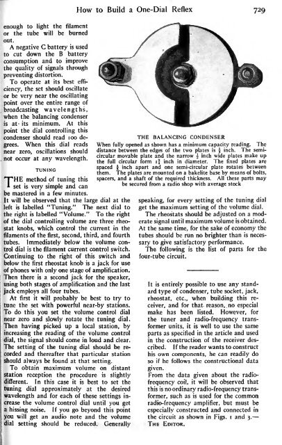
THE BALANCING CONDENSER<br />
When fully opened as shown has a minimum capacity reading. The<br />
distance between the edges of the two plates is | inch. The semicircular<br />
movable plate and the narrow \ inch wide plates make up<br />
the full circular form if inch in diameter. The fixed plates are<br />
spaced \ inch apart and one semi-circular plate rotates between<br />
them. The plates are mounted on a bakelite base by means of bolts,<br />
spacers, and a shaft of the required thickness. All these parts may<br />
be secured from a radio shop with average stock<br />
speaking, for every setting of the tuning dial<br />
get the maximum setting of the volume dial.<br />
The rheostats should be adjusted on a moderate<br />
signal until maximum volume is obtained.<br />
At the same time, for the sake of economy the<br />
tubes should be run no brighter than is necessary<br />
to give satisfactory performance.<br />
The following is the list of parts for the<br />
four-tube circuit.<br />
It is entirely possible to use any standard<br />
type of condenser, tube socket, jack,<br />
rheostat, etc., when building this receiver,<br />
and for that reason, no especial<br />
make has been listed. However, for<br />
the tuner and radio-frequency transformer<br />
units, it is well to use the same<br />
in the article and used<br />
parts as specified<br />
in the construction of the receiver described.<br />
If the reader wants to construct<br />
his own components, he can readily do<br />
he follows the constructional data<br />
so if<br />
given.<br />
From the data given about the radiofrequency<br />
coil, it will be observed that<br />
this is no ordinary radio-frequency transformer,<br />
such as is<br />
used for the common<br />
but must be<br />
radio-frequency amplifier,<br />
especially constructed and connected in<br />
the circuit as shown in Figs,<br />
i and 3.<br />
THE EDITOR.


