

Radio Broadcast - 1925, February - 113 Pages ... - VacuumTubeEra
Radio Broadcast - 1925, February - 113 Pages ... - VacuumTubeEra
Radio Broadcast - 1925, February - 113 Pages ... - VacuumTubeEra

Create successful ePaper yourself
Turn your PDF publications into a flip-book with our unique Google optimized e-Paper software.
eceiving<br />
In the R. B. Lab. 719<br />
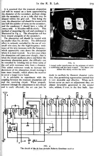
It is assumed that the resonant absorption<br />
coil will be wound on a form approximating<br />
the diameter of the secondary, perhaps alongside<br />
the secondary, or on a tube that may be<br />
slipped within the grid coil. This being the<br />
case, the absorption coil should be wound with<br />
one half the number of turns on the secondary,<br />
and the condenser C should have a value of<br />
.00025 m W. A Micadon will do nicely. This<br />
method of mounting the coil and condenser is<br />
illustrated in Fig. 3. The absorption coil has<br />
been wound alongside of the secondary.<br />
The absorption coil should be wound with<br />
no smaller than No. 26 wire. The differential<br />
effect is curiously curtailed by the use of very<br />
small wire sizes, for the high-frequency resistance<br />
of the wire increases with the frequency,<br />
which appreciably cuts down the absorption<br />
where it is most wanted. In a few cases when<br />
the absorption coil tunes over sharply, that is<br />
when the circuit oscillates above and below the<br />
maximum absorption point, the difficulty can<br />
be remedied by winding two or three turns of<br />
the coil with resistance wire from a rheostat.<br />
This added resistance tends to increase the<br />
decrement of the absorption circuit making it<br />
tune more broadly, which allows the receiver<br />
to cover a larger wave band.<br />
It is advisable to experiment with the<br />
coupling between the resonant absorption coil<br />
and the circuit. When .<br />
properly<br />
adjusted (though the adjustment is not critical<br />
and is easily effected), the set can just be<br />
FIG. 3<br />
A tuned radio transformer on the primary of which<br />
a stabilizing coil has been wound. The shunt condenser<br />
fits nicely within the tube<br />
made to oscillate by filament rheostat variation,<br />
thus permitting regeneration control that<br />
desirable and effective. When oscil-<br />
is<br />
very<br />
lations occur on such an adjustment they are<br />
almost invariably generated in the second<br />
tube, seldom, if ever, in the first bulb. Ape-<br />
FIG. 4<br />
The circuit of the de luxe six-tube Roberts Knockout receiver


