

Radio Broadcast - 1925, February - 113 Pages ... - VacuumTubeEra
Radio Broadcast - 1925, February - 113 Pages ... - VacuumTubeEra
Radio Broadcast - 1925, February - 113 Pages ... - VacuumTubeEra

You also want an ePaper? Increase the reach of your titles
YUMPU automatically turns print PDFs into web optimized ePapers that Google loves.
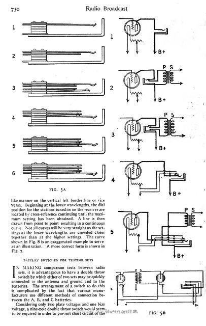
750 <strong>Radio</strong> <strong>Broadcast</strong><br />
f B+<br />
P<br />
S<br />
P<br />
S<br />
FIG.<br />
5A<br />
like manner on the vertical left border line or vice<br />
versa. Beginning at the lower wavelengths, the dial<br />
position for the stations tuned-in on the receiver are<br />
located by cross-reference continuing until the maximum<br />
setting has been obtained. A line is then<br />
drawn from point to point resulting in a continuous<br />
curve. Not all curves will be very straight as the settings<br />
at the lower wavelengths are crowded closer<br />
together than at the higher settings. The curve<br />
shown in Fig. 8 is an exaggerated example to serve<br />
as an illustration. A more correct form is shown in<br />
Fig- 7-<br />
BATTERY SWITCHES FOR TESTING SETS<br />
MAKING comparison tests between radio<br />
sets, it is advantageous to have a double throw<br />
INswitch by which either of two sets may be quickly<br />
connected to the antenna and ground and to the<br />
batteries. The arrangement of a switch to do this<br />
is complicated by the fact that various manufacturers<br />
use different methods of connection between<br />
the A, B, and C batteries.<br />
Considering only two plate voltages and one bias<br />
voltage, a nine-pole double throw switch would seem<br />
to be required in order to prevent short circuit of the FIG. 58


