

Radio Broadcast - 1925, February - 113 Pages ... - VacuumTubeEra
Radio Broadcast - 1925, February - 113 Pages ... - VacuumTubeEra
Radio Broadcast - 1925, February - 113 Pages ... - VacuumTubeEra

Create successful ePaper yourself
Turn your PDF publications into a flip-book with our unique Google optimized e-Paper software.
The Grid 747<br />
structed as a portable set, having the batteries contained<br />
in the cabinet as a part of the receiver. A<br />
loop consisting of about 12 turns of No. 18 d.c.c.<br />
wire wound on a 2 ft.<br />
square frame, shunted by a<br />
.0005 mfd. condenser will effectively cover the<br />
broadcast range of wavelengths. The use of an<br />
antenna and coupler is inadvisable as the chances<br />
for radiation are too great. The radio-frequency<br />
transformers to be used in this circuit are of the<br />
untuned type having an average wavelength range<br />
of 200 to 550 meters. If it is desired, the tuned type<br />
of transformer with a variable condenser shunting<br />
each secondary may be employed, but the tuning becomes<br />
increasingly difficult for each stage used.<br />
FIG. I<br />
The potentiometer allows the circuit to be adjusted<br />
to its most efficient point of operation and also controls<br />
to a large degree the tendency of the receiver<br />
into proper operating condition. Here, the radiofrequency<br />
amplifier with reflexed audio amplifier is to oscillate. As a further oscillation control it may<br />
eliminated from the main circuit so that the result be necessary to connect the return lead of the grid<br />
is a straight three-circuit regenerative receiver. circuits of the second and third tubes to the potentiometer<br />
arm.<br />
The primary of the audio-frequency transformer is<br />
shorted and a pair of phones inserted in series in the<br />
A THREE-TUBE R. F.-A. F. REFLEX RECEIVER<br />
plate lead of the detector tube. The first tube is<br />
removed from the socket and the antenna and<br />
ground are connected to the plate terminal of the<br />
first socket and the 890 post, respectively. By MR. T. L. G. asks for a circuit consisting of<br />
two stages of radio-frequency amplification,<br />
crystal detector, one stage of reflexed<br />
bringing the tickler close to the secondary and rotating<br />
the variable condenser, a regenerative squeal stage of radio and a stage of straight audio. This<br />
audio-frequency amplification through the second<br />
should be heard in the phones and if the detector circuit appears in Fig. 3.<br />
One rheostat of ten ohms<br />
responds correctly, carrier waves of transmitting is sufficient for controlling all three tubes. The<br />
stations will be tuned-in. If this is not the case radio-frequency transformers used are standard<br />
then the coils should be inspected for reversals of neutroformers, the secondaries of which are shunted<br />
connections, or reversals of windings. The grid by .00037 mfd. condensers. The audio reflex transformer<br />
should be of a low ratio as should the stage<br />
leak and condenser may be defective or the tube is<br />
not making proper contact with the socket blades. of straight audio. A C-battery<br />
is inserted in the<br />
By means of a progressive trouble-elimination reflex stage and the last audio stage for stabilization<br />
system it is possible finally tomake the necessary corrections<br />
so that the first tube in the radio-frequency shown allow the use of two or three tubes. In this<br />
purposes. Two jacks situated in the circuit as<br />
amplifier circuit may again be thrown in and the circuit it is absolutely essential that a good crystal<br />
operation observed. Other trouble-shooting suggestions<br />
were contained in the January, <strong>1925</strong>, GRID. throughout.<br />
be used for satisfactory results. uv-2Oi-A's are used<br />
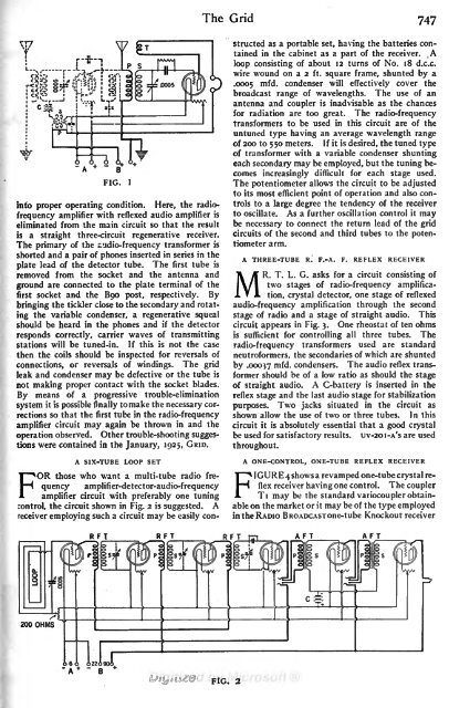
A SIX-TUBE LOOP SET<br />
A ONE-CONTROL, ONE-TUBE REFLEX RECEIVER<br />
those who want a multi-tube radio frequency<br />
amplifier-detector-audio-frequency<br />
flex receiver having one control. The<br />
4 shows a revamped one-tube crystal re-<br />
FOR<br />
coupler<br />
amplifier circuit with preferably one tuning FIGURE Ti may be the standard variocoupler obtainable<br />
on the market or it may be of the type employed<br />
control, the circuit shown in Fig. 2 is suggested. A<br />
receiver employing such a circuit may be easily con- in the RADIO BROADCAST one-tube Knockout receiver<br />
AFT<br />
AFT<br />
FIG. 2


