

Radio Broadcast - 1925, February - 113 Pages ... - VacuumTubeEra
Radio Broadcast - 1925, February - 113 Pages ... - VacuumTubeEra
Radio Broadcast - 1925, February - 113 Pages ... - VacuumTubeEra

Create successful ePaper yourself
Turn your PDF publications into a flip-book with our unique Google optimized e-Paper software.
:<br />
726 <strong>Radio</strong> <strong>Broadcast</strong><br />
From the binding post marked " +A" run a<br />
wire to each socket terminal marked " + F".<br />
From the binding post marked " A" run a<br />
wire to one terminal of the filament switch.<br />
From the other switch terminal run a wire to<br />
one terminal of each rheostat. The other<br />
three terminals of the rheostats are connected<br />
respectively to each socket terminal marked<br />
"<br />
F". The filament circuit is now completed.<br />
As each wire is<br />
put in place<br />
it is well<br />
to mark it off on the circuit diagram with a<br />
red or blue pencil.<br />
The antenna-grid circuit is wired as follows:<br />
Run a wire from the tuner terminal marked<br />
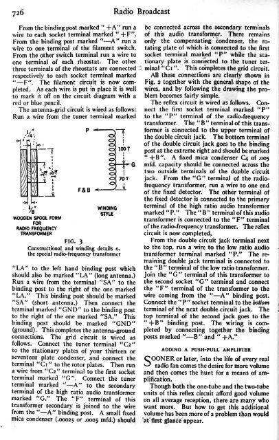
WOODEN SPOOL FORM<br />
FOR<br />
RADIO FREQUENCY<br />
TRANSFORMER<br />
FIG. 3<br />
F&B<br />
WINDING<br />
STYLE<br />
Constructional and winding details o.<br />
the special radio-frequency transformer<br />
"LA" to the left hand binding post which<br />
should also be marked "LA" (long antenna.)<br />
Run a wire from the terminal "SA" to the<br />
binding post to the right of the one marked<br />
"LA." This binding post should be marked<br />
"SA" (short antenna.) Then connect the<br />
terminal marked "GND" to the binding post<br />
to the right of the one marked "SA." This<br />
binding post should be marked "GND"<br />
(ground). This completes the antenna-ground<br />
connections. The grid circuit is wired as<br />
follows. Connect the tuner terminal "C2"<br />
to the stationary plates of your thirteen or<br />
seventeen plate condenser, and connect the<br />
terminal "Ci " to the rotor plates. Then run<br />
a wire from "C2" terminal to the first socket<br />
terminal marked "G". Connect the tuner<br />
terminal marked " -A" to the secondary<br />
terminal of the high ratio audio transformer<br />
marked "G." The "F" terminal of this<br />
transformer secondary is<br />
joined to the wire<br />
from the " A" binding post. A small fixed<br />
mica condenser (.00025 or -0005 mfd.) should<br />
be connected across the secondary terminals<br />
of this audio transformer. There remains<br />
only the compensating condenser, the rotating<br />
plate of which is connected to the first<br />
socket terminal marked "P" while the stationary<br />
plate<br />
is connected to the tuner terminal<br />
"Ci ". This completes the grid circuit.<br />
All these connections are clearly shown in<br />
Fig. 2 together with the general shape of the<br />
wires, and by following the drawing the problem<br />
becomes fairly simple.<br />
The reflex circuit is wired as follows. Connect<br />
the first socket terminal marked "P"<br />
to the "P" terminal of the radio-frequency<br />
transformer. The " B " terminal of this transformer<br />
is connected to the upper terminal of<br />
the double circuit jack. The bottom terminal<br />
of the double circuit jack goes to the binding<br />
post at the extreme right and should be marked<br />
"+B". A fixed mica condenser C^ of .005<br />
mfd. capacity should be connected across the<br />
two outside terminals of the double circuit<br />
jack. From the "G" terminal of the radiofrequency<br />
transformer, run a wire to one end<br />
of the fixed detector. The other terminal of<br />
the fixed detector is connected to the primary<br />
terminal of the high ratio audio transformer<br />
marked " P." The " B " terminal of this audio<br />
transformer is connected to the "F" terminal<br />
of the radio-frequency transformer. The reflex<br />
circuit is now completed,<br />
From the double circuit jack terminal next<br />
to the top, run a wire to the low ratio audio<br />
transformer terminal marked "P." The remaining<br />
double jack terminal is connected to<br />
the " B" terminal of the low ratio transformer.<br />
Join the "G" terminal of this transformer to<br />
the second socket "G" terminal and connect<br />
the "F" terminal of the transformer to the<br />
wire coming from the " A" binding post.<br />
Connect the "P" socket terminal to the bottom<br />
terminal of the next double circuit jack. The<br />
top terminal of the second jack goes to the<br />
'+B" binding post. The wiring<br />
is completed<br />
by connecting together the binding<br />
posts marked " B" and " +A."<br />
ADDING A<br />
COONER or later,<br />
PUSH-PULL AMPLIFIER<br />
into the life of every<br />
^ real<br />
radio fan comes the desire for more volume<br />
and then comes the hunt for a means of amplification.<br />
Though both the one-tube and the two-tube<br />
units of this reflex circuit afford good volume<br />
on all<br />
average reception, there are many who<br />
want more. But how to get this additional<br />
volume has been more of a problem than would<br />
at first glance appear.


