

Radio Broadcast - 1925, February - 113 Pages ... - VacuumTubeEra
Radio Broadcast - 1925, February - 113 Pages ... - VacuumTubeEra
Radio Broadcast - 1925, February - 113 Pages ... - VacuumTubeEra

Create successful ePaper yourself
Turn your PDF publications into a flip-book with our unique Google optimized e-Paper software.
How to Build a One-Dial Reflex 725<br />
INSIDE<br />
The " works." As can be seen, the wiring for this receiver<br />
is not difficult and the layout parts quite easy to duplicate<br />
reset, a different resistance will be introduced<br />
necessitating a retuning of the entire circuit.<br />
This is particularly annoying<br />
if the station<br />
that is<br />
being received is a distant one. This<br />
difficulty is entirely eliminated when a fixed<br />
type of crystal detector is used.<br />
THE RADIO-FREQUENCY TRANSFORMER<br />
D EFERRING to Fig.<br />
i once more it will<br />
1^- be noted that the radio-frequency transformer<br />
used, is of unique design and is especially<br />
built to give maximum amplification over<br />
the broadcasting wavelengths when used between<br />
a tube and a crystal detector. It has a<br />
step down ratio and will not function between<br />
two tubes as is the case with the ordinary<br />
radio-frequency transformer.<br />
Its construction is as follows:<br />
On a spool if" in diameter and f" wide, having a<br />
slot \" wide and \" deep are wound 170 turns of No.<br />
35 wire.<br />
First, 70 turns are wound in the slot and a tap<br />
taken off which connects to G, then too turns are<br />
wound over this, the end connecting to P.<br />
The beginning of the winding connects to F and<br />
B. See Figs,<br />
i & 3.<br />
WIRING THE SET<br />
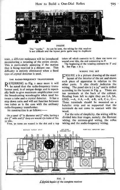
FIGURE 2 is a picture drawing of the exact<br />
layout of the interior of the set and shows<br />
each piece of apparatus in relation to the<br />
other parts. It also clearly indicates the<br />
wiring. The panel size is<br />
7 x 24" and is drilled<br />
according to the layout in Fig. 4. There are<br />
ten terminals at the back of the cabinet.<br />
Reading from left to right they are LA, SA,<br />
GND, A, +A, B, + B, + B, C+, C .<br />
These terminals should be mounted on a<br />
bakelite strip and so supported that the<br />
terminals do not come in contact with the<br />
wood.<br />
For the sake of simplicity, the wiring will be<br />
divided into four stages, namely, the filament<br />
wiring, the antenna-grid wiring,<br />
wiring and the audio-frequency wiring.<br />
the reflex<br />
REFLEX TUNER U N 11 PUSH-PULL AMPLIFIER UNIT<br />
FIG. 2<br />
A picture layout of the complete receiver


