

Radio Broadcast - 1925, February - 113 Pages ... - VacuumTubeEra
Radio Broadcast - 1925, February - 113 Pages ... - VacuumTubeEra
Radio Broadcast - 1925, February - 113 Pages ... - VacuumTubeEra

You also want an ePaper? Increase the reach of your titles
YUMPU automatically turns print PDFs into web optimized ePapers that Google loves.
In the R. B. Lab. 721<br />
This resistance is<br />
bypassed by a i mfd. condenser<br />
C. The resistance probably also has<br />
A dampening effect on the radio-frequency<br />
fluctuations in the plate current, thus reducing<br />
feed-back through the capacity of the tube.<br />
Because of this, it is not necessary to reduce<br />
the plate voltage below the efficient operating<br />
potentials of the amplifying tubes in the radio<br />
frequency circuit.<br />
A SIX-TUBE ROBERTS RECEIVER<br />
4, 5, and 6 illustrate a special<br />
Roberts Knockout receiver<br />
FIGURES<br />
built, from<br />
data supplied by RADIO BROADCAST,<br />
by Schneider and Horneij of New York.<br />
The receiver employs the standard Roberts<br />
tuning arrangement followed by four stages of<br />
resistance-coupled amplification. The receiver<br />
is de luxe in every respect, only a few of the<br />
refinements being brought out in the photographs<br />
and diagram.<br />
Referring to the diagram, Fig. 4, the apparatus<br />
to the left of the dotted line is identical<br />
with the usual Roberts equipment. Ci<br />
throughout the circuit, is a .012 mfd. fixed condenser.<br />
Ca is a mfd. i<br />
bypass condenser.<br />
Filament control jacks were used in the actual<br />
receiver, though for simplicity the auxiliary<br />
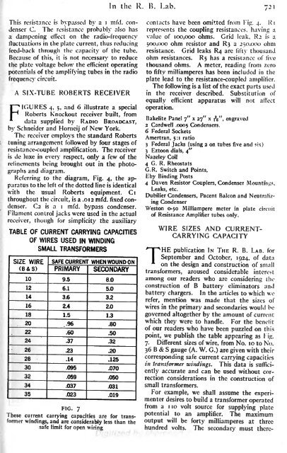
SIZE WIRE<br />
(B&S)


