

Radio Broadcast - 1925, February - 113 Pages ... - VacuumTubeEra
Radio Broadcast - 1925, February - 113 Pages ... - VacuumTubeEra
Radio Broadcast - 1925, February - 113 Pages ... - VacuumTubeEra

You also want an ePaper? Increase the reach of your titles
YUMPU automatically turns print PDFs into web optimized ePapers that Google loves.
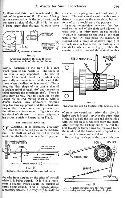
A Winder for Small Inductances 739<br />
As illustrated this result is obtained by the<br />
ratio of the gears A and B. The gear A being<br />
on the same shaft with the coil, its rotating is<br />
the same as that of the coil, while the gear<br />
B being larger than the gear A, turns more<br />
PITCH SPIRAL THROUGH 180<br />
BRASS BUSHING<br />
PRESS FIT IN CAM<br />
error in attempting to count and wind by<br />
hand. The writer used a motor with a worm<br />
drive with a gear on the main shaft, but an><br />
form of drive would serve the purpose.<br />
In using the machine, the wire is first fastened<br />
on the end of the shaft and allowed to<br />
wind twenty or thirty turns on the bushing<br />
D which is<br />
clamped on the end of the shaft<br />
\vith a nut. At this point the machine is<br />
stopped and a piece of adhesive tape f of<br />
an inch wide is laid across the bushing with<br />
the sticky side up as in Fig. 7.<br />
Then the<br />
counter is set at zero and the desired number<br />
FIG. 5<br />
A working sketch of the cam, the most<br />
important unit of the entire device<br />
slowly. Fastened to the gear B is a cam<br />
which operates the nozzle C. The shape of<br />
this cam is very important. The rate of<br />
travel of the nozzle should be constant with<br />
practically no time-interval at the end of the<br />
travel when the direction is reversed. Therefore,<br />
the ideal shape<br />
a straight spiral through 180<br />
of the cam is that of<br />
and the reverse<br />
spiral through the remaining 180. There is<br />
absolutely ho way that this cam can be cut<br />
except on an end milling machine with a<br />
double motion. Any up-to-date machine<br />
shop has this equipment and the actual cutting<br />
of the cam is a very short process after<br />
the milling machine is set up. Fig. 5<br />
is a working<br />
sketch of this cam. Its lateral reciprocating<br />
action is plainly illustrated in Fig. 6.<br />
THE WINDING MACHINE<br />
OF COURSE, it is absolutely necessary<br />
that there is no end play in the mechanism.<br />
The shaft on which the coil is wound<br />
must run absolutely true in order to prevent<br />
- GEAR AND CAM BOTH<br />
/'PRESS FIT ON BUSHING<br />
FIG. 7<br />
Preparing the coil for binding with adhesive tape<br />
of turns are wound on. After this, the adhesive<br />
tape is brought up over the outer edge<br />
of the coil to hold the last turn and the bushing<br />
with the coil on it is removed from the shaft.<br />
After driving the bushing out of the coil the<br />
first twenty or thirty turns are removed from<br />
the inside and the finished coil is<br />
dipped in a<br />
mixture of acetone and celluloid.<br />
By varying the shape of the cam which con-<br />
COIL<br />
ROLLER<br />
GUIDESft<br />
ROD FREE TO TURN<br />
,' AS COIL BUILDS UP<br />
LATERAL MOVEMENT<br />
FIG. 6<br />
O rfWWWWWW J<br />
SPRING TO KEEP ROD<br />
AGAINST FACE OF CAM<br />
Illustrates the function of the cam and nozzle<br />
the wire from slipping on the edges of the coil<br />
while it is being wound. D in Fig. 2 represents<br />
a counter which counts the number of<br />
turns being wound. This is likewise almost<br />
a necessitv because it is verv casv to make an<br />
FIG. 8<br />
A detail showing how the roller with<br />
spring tension keeps the layers in place


