

Radio Broadcast - 1925, February - 113 Pages ... - VacuumTubeEra
Radio Broadcast - 1925, February - 113 Pages ... - VacuumTubeEra
Radio Broadcast - 1925, February - 113 Pages ... - VacuumTubeEra

Create successful ePaper yourself
Turn your PDF publications into a flip-book with our unique Google optimized e-Paper software.
748 <strong>Radio</strong> <strong>Broadcast</strong><br />
and will not be repeated here.<br />
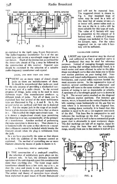
RADIO FREQUENCY AMPLIFIER NEUTROFORMERS CRYSTAL DETECTOR<br />
'<br />
P S UV 201 A PS UV 201 A P<br />
The<br />
- S<br />
P S UV201A<br />
suggested circuit is shown in<br />
Fig. 6. Any standard type of<br />
tubes may be used in a unit of<br />
this kind but of course uv-2Oi-A's<br />
or better still, power tubes such as<br />
the 202 or the w. E. 2i6-A will be<br />
more suitable for this type of work.<br />
The value of C battery will vary<br />
in proportion to the amount of B<br />
battery used. A table of C battery<br />
voltages was included in THE GRID<br />
for January, <strong>1925</strong>. For the tubes<br />
-<br />
-<br />
A + B<br />
suggested<br />
FIG. 120 to 150 volts B battery<br />
will be sufficient.<br />
as explained in the April, 1924, RADIO BROADCAST,<br />
CALIBRATION CURVES<br />
3<br />
The radio-frequency transformer T2 is of the untuned<br />
type and covers a wavelength range of 200 to<br />
any type of receiver may be charted<br />
5,0 meters. Much<br />
and calibrated so that a<br />
of the instruction as outlined for<br />
the three-tube circuit of Fig. 3<br />
ALMOST<br />
graphical curve is<br />
may be followed in<br />
produced that may be used for reference<br />
the construction of this receiver. Especial care purposes. Instead of rumaging through numerous<br />
should be exercised in the selection of a suitable papers having dial settings numerically listed, it is<br />
audio-frequency transformer and much easier and more efficient to refer to the s.hipshape<br />
wavelength curve that also helps you to locate<br />
crystal.<br />
JACKS, AND HOW THEY ARE USED<br />
new station positions on your tuning dial. Neutrodyne<br />
and tuned radio-frequency receivers, superhetrodynes,<br />
and crystal reflex receivers furnish the<br />
are as many types of closed circuit<br />
jacks as there are manufacturers of them.<br />
most<br />
THERE<br />
It should be remembered that jacks are used<br />
accurate curves. In the regenerative type of<br />
for the sole purpose of receiver, several combinations of inductance and<br />
providing a mechanical cutin<br />
on any part of a radio circuit. In the natural<br />
capacity will tune to the same station and the curve<br />
progress of system<br />
things, jacks came to be used in more<br />
of tuning is not so dependable or reliable.<br />
A specimen of a wavelength graph curve is shown in<br />
elaborate ways. One manufacturer produces 14<br />
Fig.<br />
different kinds of jacks. Not all of them can 8. The several points marked on the diagonal<br />
be<br />
line indicate station positions. For instance 492<br />
explained here but several of the more well-known<br />
meters, WEAF, is located on the vertical border to the<br />
type are illustrated in Fig. 5, A and B. In A, the<br />
left; running<br />
several styles are outlined and rcross horizontally on the 492 line we<br />
their use is depicted<br />
in B. For the output jack in the stage of an note where it is intersected by the diagonal line.<br />
amplifier<br />
or a plain detector circuit we have that as shown<br />
Then, coming down vertically, it is found that this<br />
position is equal to 81 on a 100 segment semi-circle<br />
in i . This is called the single open-circuit type.<br />
I n<br />
of the dial. This base line is comparative to and<br />
2 is shown a single-closed circuit type permitting indicates the<br />
the throwing in or markings on the dial. To<br />
out, automatically, of the prepare a<br />
primary wavelength<br />
of a transformer. Another method curve it is well to have commercial graph<br />
of performing paper<br />
the same operation<br />
is shown in 3. That shown that is obtainable in most stationery shops.<br />
in 4<br />
is<br />
fundamentally the same as that shown The dial markings are laid off at regular, equal intervals<br />
along the base line and the wavelength<br />
in i except<br />
that a filament control is included which breaks the<br />
filament circuit when the range, usually from 200 to 600 meters is hid off in a<br />
plug<br />
is withdrawn from<br />
the jack.<br />
UNTUNED<br />
In 5 we have practically the same as that shown<br />
RFT<br />
in 2 with the addition of the filament control as<br />
explained. The method of controlling one or more<br />
V T I<br />
T 2<br />
filament circuits by means of jacks is shown in 6.<br />
A PUSH-PULL POWER AMPLIFIER<br />
THE construction of a push-pull amplifier,<br />
the selection of satisfactory parts plays an im-<br />
role. In fact, the ultimate successful<br />
INportant<br />
operation of the unit depends upon this consideration<br />
more than anything else. The input stage audio<br />
transformer should have a low ratio, say 2 to i, so<br />
that the voice and music is not unnecessarily distorted<br />
before it reaches the push-pull transformers.<br />
The action and theory of operation have already<br />
been explained in past issues of RADIO BROADCAST


