RTL8181 Wireless LAN Access Point/Gateway Controller DATA ...
RTL8181 Wireless LAN Access Point/Gateway Controller DATA ...
RTL8181 Wireless LAN Access Point/Gateway Controller DATA ...
- No tags were found...

Create successful ePaper yourself
Turn your PDF publications into a flip-book with our unique Google optimized e-Paper software.
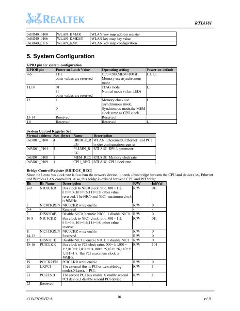
<strong>RTL8181</strong>0xBD40_0100 W<strong>LAN</strong>_KMAR W<strong>LAN</strong> key map address register0xBD40_0106 W<strong>LAN</strong>_KMKEY W<strong>LAN</strong> key map key value0xBD40_0116 W<strong>LAN</strong>_KMC W<strong>LAN</strong> key map configuration5. System ConfigurationGPIO pin for system configurationGPIOB pin Power on Latch Value Operating setting Power on default9-6 1111other values are reservedCPU=200,MEM=100 ifMemory use asynchronous1,1,1,111,10 0111other values are reserved13 10modeJTAG modeNormal mode (wlan LED)Memory clock useasynchronous mode.Synchronous mode,the MEMclock same as CPU clock15-14 Reserved Reserved1,0 Reserved Reserved 1,1System Control Register SetVirtual address Size (byte) Name Description0xBD01_0100 4 BRIDGE_REGW<strong>LAN</strong>, Eherernet0, Ethernet1 and PCIbridge configuration register0xBD01_0104 4 PLLMN_R <strong>RTL8181</strong> DPLL parameterEG0xBD01_0108 1 MEM_REG <strong>RTL8181</strong> Memory clock rate0xBD01_0109 1 CPU_REG <strong>RTL8181</strong> CPU clock rateBridge Control Register (BRIDGE_REG)Since the Lexra bus clock rate is fast than the network device, it needs a bus bridge between the CPU and device (i.e., Ethernetand <strong>Wireless</strong> <strong>LAN</strong> controller). Also, this bridge is existed between CPU and PCI bridge.Bit Bit Name Description R/W InitVal2-0 NIC0CKR Bus clock to NIC0 clock ratio. 001= 1:2, R/W 011011=1:4,101=1:6,111=1:8 ,other valuereserved. The NIC0 and NIC1 maximum clockis 50MHz.3 NIC0CKREN NIC0CKR write enable R/W 06-4 - Reserved - -7 DISNIC0B Disable NIC0,0 enable NIC0, 1 disable NIC0 R/W 010-8 NIC1CKR Bus clock to NIC1 clock ratio. 001= 1:2, R/W 011011=1:4,101=1:6,111=1:8 ,other valuereserved11 NIC1CKREN NIC0CKR write enable R/W 014-12 - Reserved R/W 015 DISNIC1B Disable NIC1,0 enable NIC1, 1 disable NIC1 R/W 018-16 PCICLKR Bus clock to PCI clock ratio. 000=1:1,001= R/W 1011:2,010=1:3,011=1:4,100=1:5,101=1:6,110=1:7,111=1:8. The PCI maximum clock is50MHz.19 PCICKREN PCICLKR write enable R/W 020 LXPCI The external Bus is PCI or Lexra(debug R/W 1mode).0 Lexra, 1 PCI.21 PCI2ENB The second PCI bus enable. 0 enable second R/W 1PCI device,1 disable second PCI device22 Reserved1,1116CONFIDENTIAL v1.0