RTL8181 Wireless LAN Access Point/Gateway Controller DATA ...
RTL8181 Wireless LAN Access Point/Gateway Controller DATA ...
RTL8181 Wireless LAN Access Point/Gateway Controller DATA ...
- No tags were found...

You also want an ePaper? Increase the reach of your titles
YUMPU automatically turns print PDFs into web optimized ePapers that Google loves.
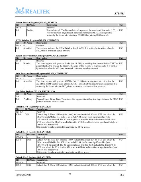
<strong>RTL8181</strong>Beacon Interval Register (W<strong>LAN</strong>_BCNITV)Bit Bit Name Description R/W15-10 - Reserved -9-0 BcnItv Beacon Interval: The Beacon Interval represents the number of time units (1 TU = R/W1024µs) between target beacon transmission times (TBTTs). This register iswritten by the driver after starting a BSS/IBSS or joining IBSS network.ATIM Window Register (W<strong>LAN</strong>_ATIMWND)Bit Bit Name Description R/W15-10 -- Reserved9-0 AtimWnd This register indicates the ATIM Window length in TU. It is written by the driver after theNIC joins or creates an adhoc network.R/WBeacon Interrupt Interval Register (W<strong>LAN</strong>_BINTRITV)Bit Bit Name Description R/W15-10 - Reserved9-0 BintrItv This timer register will generate BcnInt (bit 13, ISR) at a setting time interval before TBTT to R/Wprompt the host to prepare the beacon. The units of this register is microseconds. It is writtenby the driver after the NIC joins a network or creates an adhoc network.Atim Interrupt Interval Register (W<strong>LAN</strong>_ATIMTRITV)Bit Bit Name Description R/W15-10 - Reserved9-0 AtimtrItv This timer register will generate ATIMInt (bit 12, ISR) at a setting time interval before theend of the ATIM window in an adhoc network. The units of this register is microseconds. It iswritten by the driver after the NIC joins a network or creates an adhoc network.R/WPhy Delay Register (W<strong>LAN</strong>_PHYDELAY)Bit Bit Name Description R/W7-3 - Reserved -2-0 PhyDelay Physical Layer Delay Time: These three bits represent the delay time in µs between the MAC R/Wand RF front end when Tx data.Default Key 0 Register (W<strong>LAN</strong>_DK0)Bit Bit Name Description R/W127-104 - Reserved -103-0 DK0 Default Key 0: These 104 bits (bits 103:0) indicate the default 104-bit WEP key, which theID is 0 when KM (bits 5:4, SCR) is set to WEP104, the 24 most significant bits (bits127:103) will be reserved. The 40 least significant bits (bits 39:0) indicate the default 40-bitWEP key, which the ID is 0 when KM is set to WEP40, and the 64 most significant bits (bits103:40) will be reserved.This register is only permitted to read/write by 4-byte access.R/WDefault Key 1 Register (W<strong>LAN</strong>_DK1)Bit Bit Name Description R/W127-104 - Reserved -103-0 DK1 Default Key 1: These 104 bits (bits 103:0) indicate the default 104-bit WEP key, which theID is 1 when KM (bits 5:4, SCR) is set to WEP104, the 24 most significant bits (bits127:103) will be reserved. The 40 least significant bits (bits 39:0) indicate the default 40-bitWEP key, which the ID is 1 when KM is set to WEP40, and the 64 most significant bits (bits103:40) will be reserved.This register is only permitted to read/write by 4-byte access.R/WDefault Key 2 Register (W<strong>LAN</strong>_DK2)Bit Bit Name Description R/W127:104 - Reserved -103:0 DK2 Default Key 2: These 104 bits (bits 103:0) indicate the default 104-bit WEP key, which the R/W45CONFIDENTIAL v1.0