RTL8181 Wireless LAN Access Point/Gateway Controller DATA ...
RTL8181 Wireless LAN Access Point/Gateway Controller DATA ...
RTL8181 Wireless LAN Access Point/Gateway Controller DATA ...
- No tags were found...

You also want an ePaper? Increase the reach of your titles
YUMPU automatically turns print PDFs into web optimized ePapers that Google loves.
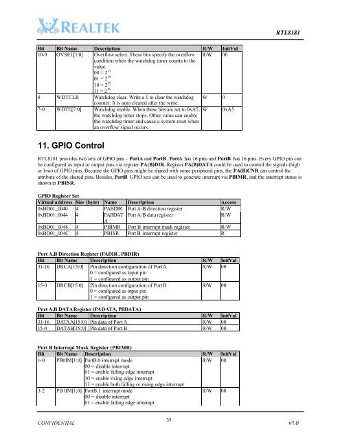
<strong>RTL8181</strong>Bit Bit Name Description R/W InitVal10-9 OVSEL[1:0] Overflow select. These bits specify the overflow R/W 0011 = 2 16condition when the watchdog timer counts to thevalue.00 = 2 1301 = 2 1410 = 2 158 WDTCLR Watchdog clear. Write a 1 to clear the watchdog W 0counter. It is auto cleared after the write.7-0 WDTE[7:0] Watchdog enable. When these bits are set to 0xA5, W 0xA5the watchdog timer stops. Other value can enablethe watchdog timer and cause a system reset whenan overflow signal occurs.11. GPIO Control<strong>RTL8181</strong> provides two sets of GPIO pins – PortA and PortB . PortA has 16 pins and PortB has 16 pins. Every GPIO pin canbe configured as input or output pins via register PA(B)DIR. Register PA(B)<strong>DATA</strong> could be used to control the signals (highor low) of GPIO pins. Because the GPIO pins might be shared with some peripheral pins, the PA(B)CNR can control theattribute of the shared pins. Besides, PortB GPIO sets can be used to generate interrupt via PBIMR, and the interrupt status isshown in PBISR.GPIO Register SetVirtual address Size (byte) Name Description <strong>Access</strong>0xBD01_0040 4 PABDIR Port A/B direction register R/W0xBD01_0044 4 PABDAT Port A/B data registerR/WA0xBD01_0048 4 PBIMR Port B interrupt mask register R/W0xBD01_004C 4 PBISR Port B interrupt register RPort A,B Direction Register (PADIR , PBDIR)Bit Bit Name Description R/W InitVal31-16 DRCA[15:0] Pin direction configuration of Port AR/W 000 = configured as input pin1 = configured as output pin15-0 DRCB[15:0] Pin direction configuration of Port B0 = configured as input pin1 = configured as output pinR/W 00Port A,B <strong>DATA</strong> Register (PA<strong>DATA</strong>, PB<strong>DATA</strong>)Bit Bit Name Description R/W InitVal31-16 <strong>DATA</strong>A[15:0] Pin data of Port A R/W 0015-0 <strong>DATA</strong>B[15:0] Pin data of Port B R/W 00Port B Interrupt Mask Register (PBIMR)Bit Bit Name Description R/W InitVal1-0 PB0IM[1:0] PortB.0 interrupt modeR/W 0000 = disable interrupt01 = enable falling edge interrupt10 = enable rising edge interrupt11 = enable both falling or rising edge interrupt3-2 PB1IM[1:0] PortB.1 interrupt mode00 = disable interrupt01 = enable falling edge interruptR/W 0035CONFIDENTIAL v1.0