Tail Rotor Driveshaft Hanger
Tail Rotor Driveshaft Hanger
Tail Rotor Driveshaft Hanger
- No tags were found...

Create successful ePaper yourself
Turn your PDF publications into a flip-book with our unique Google optimized e-Paper software.
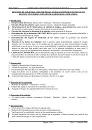
BHT-212-CR&0(b-n--1 0-ca0)0ohm^mNOTEA workaid may be fabricated (figure65-2, detail B) to aid installation ofseal (10, figure 65-2).3. Install seal (10) into outer coupling (8)seal groove as follows:ate-O`4-poiU-0+0.,E0 0a. Apply a light coat of lubricant (tubepack) (C-015) to outer circumference of seal(10).b. Install seal (10) into outer coupling (8)seal groove with lip of seal toward internalsplines to outer coupling (8), as shown infigure 65-2, detail A.NOTESeal (10) will be partially seated andinner coupling (7) will be used as abackup, in reverse (see detail A) tofully seat outer circumference edgeof seal into outer coupling sealgroove.C. Using inner coupling (7) as a backupand placed (detail A), firmly press down (handQ-0pressure only) on outer coupling (8),simultaneously tuck outer circumference edgeof seal (10) with workaid into outer coupling(8) seal groove.d. Continue pressing around seal (10)with workaid until seal (10) is fully seated.Remove inner coupling (7) from outercoupling (8).4. Hand pack internal splines of outercoupling (8) with lubricant (tube pack) (C-015)...to 0.12 in. (3.048mm) deep over top ofinternal splines for full length of exposedsplines. A workaid may be fabricated (figure65-2, detail C) to obtain depth of grease.((DD=..0(ODU.)NOTEEnsure inner coupling (7) is correctfor tail rotor driveshaft hangercoupling, overall length is 2.07 to2.08 in. (52.578 to 52.832 mm).0-.,.-r4-0O+,0Coupling for 42° and 90° gearbox is1.87 to 1.88 in. (47.498 to 47.752mm) long.5. Install inner coupling (7), with small endthrough seal (10). Bottom out inner couplingagainst seal.6. Assemble retainer plate (6) and rearcoupling (15) onto splined end of inner shaft(11). Install inner and outer coupling (7 and8), retainer plate (6) on opposite end of innershaft (11). Install bolt (4) through retainerplate (6) with bolt head toward coupling end,with washers (5) and nut (16). Torque nut 50to 70 in.lbs. (5.649 to 7.9086 Nm) and securewith cotter pin.7. Place spring (3) onto alignment probe on Irear side of cover plate (2). Position springand cover on outer coupling (8), compressspring and install retainer ring (1). Ensureretainer ring is fully seated.NOTERefer to paragraph 65-10 forpainting of 212-040-600-001 and -009 tail rotor driveshaft hangerassemblies.°-.0)(D65-00-00Page 10Rev.4