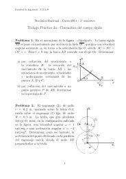
Tail Rotor Driveshaft Hanger
Tail Rotor Driveshaft Hanger
Tail Rotor Driveshaft Hanger
- No tags were found...

Create successful ePaper yourself
Turn your PDF publications into a flip-book with our unique Google optimized e-Paper software.
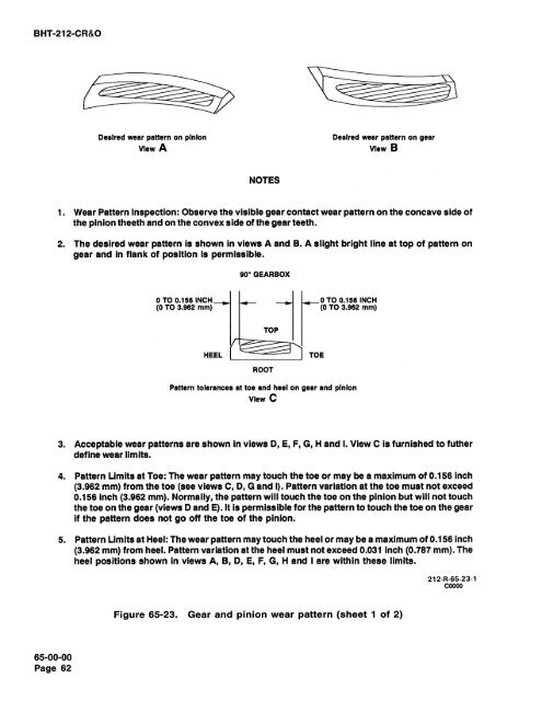
BHT-212-CR&ODesired wear pattern on pinionview ADesired wear pattern on gearview BNOTES1. Wear Pattern Inspection: Observe the visible gear contact wear pattern on the concave side ofthe pinion theeth and on the convex side of the gear teeth.2. The desired wear pattern is shown in views A and B. A slight bright line at top of pattern ongear and in flank of position is permissible.0.p90° GEARBOXROOTPattern tolerances at toe and heel on gear and pinionView C3. Acceptable wear patterns are shown in views D, E, F, G, Hand I. View C is furnished to futherdefine wear limits.4. Pattern Limits at Toe: The wear pattern may touch the toe or may be a maximum of 0.156 inch(3.962 mm) from the toe (see views C, D, G and 1). Pattern variation at the toe must not exceed0.156 inch (3.962 mm). Normally, the pattern will touch the toe on the pinion but will not touchthe toe on the gear (views D and E). It is permissible for the pattern to touch the toe on the gearif the pattern does not go off the toe of the pinion.-00532amtQ.40is.m00ash.Ccfl. Cod5. Pattern Limits at Heel: The wear pattern may touch the heel or maybe a maximum of 0.156 inch(3.962 mm) from heel. Pattern variation at the heel must not exceed 0.031 inch (0.787 mm). Theheel positions shown in views A, B, D, E, F, G, H and I are within these limits..-.+O+=.O*212-R-65-23-100000Figure 65-23. Gear and pinion wear pattern (sheet 1 of 2)'Q.65-00-00Page 62