Tail Rotor Driveshaft Hanger
Tail Rotor Driveshaft Hanger
Tail Rotor Driveshaft Hanger
- No tags were found...
You also want an ePaper? Increase the reach of your titles
YUMPU automatically turns print PDFs into web optimized ePapers that Google loves.
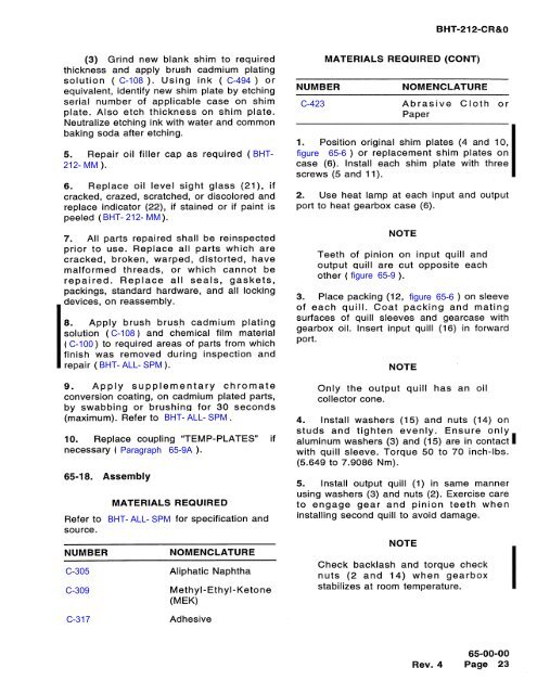
BHT-212-CR&0(3) Grind new blank shim to requiredthickness and apply brush cadmium platingsolution (C-108). Using ink (C-494) orequivalent, identify new shim plate by etchingserial number of applicable case on shimplate. Also etch thickness on shim plate.Neutralize etching ink with water and commonbaking soda after etching.-0_D))cad--aCo.:a)==c-0EJ-2 :-°5. Repair oil filler cap as required (BHT-212-MM).6. Replace oil level sight glass (21), ifcracked, crazed, scratched, or discolored andreplace indicator (22), if stained or if paint ispeeled (BHT-212-MM).7. All parts repaired shall be reinspectedprior to use. Replace all parts which arecracked, broken, warped, distorted, havemalformed threads, or which cannot berepaired. Replace all seals, gaskets,packings, standard hardware, and all lockingdevices, on reassembly.8. Apply brush brush cadmium platingsolution (C-108) and chemical film material(C-100) to required areas of parts from whichfinish was removed during inspection andrepair (BHT-ALL-SPM).033-o9. Apply supplementary chromateconversion coating, on cadmium plated parts,by swabbing or brushing for 30 seconds(maximum). Refer to BHT-ALL-SPM.10. Replace coupling "TEMP-PLATES" ifnecessary (Paragraph 65-9A).65-18. AssemblyMATERIALS REQUIREDRefer to BHT-ALL-SPM for specification andsource.0_-0zNUMBERMATERIALS REQUIRED (CONT)0fatw-wc0NOMENCLATUREC-423 Abrasive Cloth orPaper1. Position original shim plates (4 and 10,figure 65-6) or replacement shim plates oncase (6). Install each shim plate with threescrews (5 and 11).0-.(CD(D38+,2. Use heat lamp at each input and outputport to heat gearbox case (6).NOTETeeth of pinion on input quill andoutput quill are cut opposite eachother (figure 65-9).3-Q3. Place packing (12, figure 65-6) on sleeveof each quill. Coat packing and matingsurfaces of quill sleeves and gearcase withgearbox oil. Insert input quill (16) in forwardport.NOTEOnly the output quill has an oilcollector cone.4. Install washers (15) and nuts (14) onstuds and tighten evenly. Ensure onlyaluminum washers (3) and (15) are in contactwith quill sleeve. Torque 50 to 70 inch-lbs.(5.649 to 7.9086 Nm).5. Install output quill (1) in same mannerusing washers (3) and nuts (2). Exercise careto engage gear and pinion teeth wheninstalling second quill to avoid damage.NOTENUMBERNOMENCLATURECheck backlash and torque checkC-305 Aliphatic Naphthanuts (2 and 14) when gearboxC-309 Methyl-Ethyl-Ketone stabilizes at room temperature.(MEK)C-317 Adhesive65-00-00Rev.4 Page 23(DD


