Tail Rotor Driveshaft Hanger
Tail Rotor Driveshaft Hanger
Tail Rotor Driveshaft Hanger
- No tags were found...

Create successful ePaper yourself
Turn your PDF publications into a flip-book with our unique Google optimized e-Paper software.
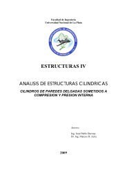
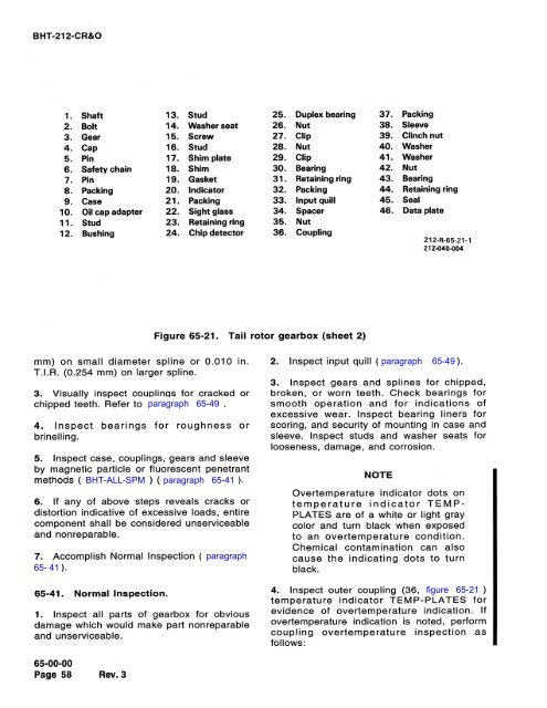
0BHT-212-CR&O1. Shaft 13. Stud 25. Duplex bearing 37. Packing2. Bolt 14. Washer seat 26. Nut 38. Sleeve3. Gear 15. Screw 27. Clip 39. Clinch nut4. Cap 16. Stud 28. Nut 40. Washer5. Pin 17. Shim plate 29. Clip 41. Washer6. Safety chain 18. Shim 30. Bearing 42. Nut7. Pin 19. Gasket 31. Retaining ring 43. Bearing8. Packing 20. Indicator 32. Packing 44. Retaining ring9. Case 21. Packing 33. Input quill 45. Seal10. Oil cap adapter 22. Sight glass 34. Spacer 46. Data plate11. Stud 23. Retaining ring 35. Nut12. Bushing 24. Chip detector 36. Coupling212-R-65-21-1212-040-004O') IS)C11W-O(NOONDa-.Figure 65-21. <strong>Tail</strong> rotor gearbox (sheet 2)mm) on small diameter spline or 0.010 in.T.I.R. (0.254 mm) on larger spline.3. Visually inspect couplings for cracked orchipped teeth. Refer to paragraph 65-49.4. Inspect bearings for roughness or(0-0brinelling.(On0)C ltd((fU-00-005. Inspect case, couplings, gears and sleeveby magnetic particle or fluorescent penetrantmethods (BHT-ALL-SPM) (paragraph 65-41).+O.6. If any of above steps reveals cracks ordistortion indicative of excessive loads, entirecomponent shall be considered unserviceableand nonreparable.7. Accomplish Normal Inspection (paragraph65-41).65-41. Normal Inspection.1. Inspect all parts of gearbox for obviousdamage which would make part nonreparableand unserviceable.65-00-00Page 58Rev.32. Inspect input quill (paragraph 65-49).3. Inspect gears and splines for chipped,broken, or worn teeth. Check bearings forsmooth operation and for indications ofM-0.-.c.>0+af11o*am-excessive wear. Inspect bearing liners forscoring, and security of mounting in case andsleeve. Inspect studs and washer seats forlooseness, damage, and corrosion.NOTEOvertemperature indicator dots ontemperature indicator TEMP-PLATES are of a white or light graycolor and turn black when exposedto an overtemperature condition.Chemical contamination can alsocause the indicating dots to turnblack.4. Inspect outer coupling (36, figure 65-21)temperature indicator TEMP-PLATES forevidence of overtemperature indication. Ifovertemperature indication is noted, performcoupling overtemperature inspection asfollows:-gym