Tail Rotor Driveshaft Hanger
Tail Rotor Driveshaft Hanger
Tail Rotor Driveshaft Hanger
- No tags were found...

Create successful ePaper yourself
Turn your PDF publications into a flip-book with our unique Google optimized e-Paper software.
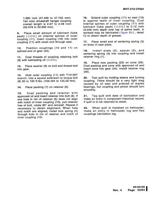
BHT-212-CR&0(J11.880 inch (47.498 to 47.752 mm).<strong>Tail</strong> rotor driveshaft hanger couplingoverall length is 2.07 to 2.08 inch(52.578 to 52.832 mm).>+,Nc9. Place small amount of lubricant (tubepack) (C-015) on internal splines of outercoupling (11). Insert coupling (10) into outercoupling (11) with small end through seal.(^D(OQ cQ)Q.7 (CD-(a10. Position couplings (10 and 11) onsplined end of gear (24).11. Coat threads of coupling retaining bolt(8) with lubricating oil (C-010).12. Place washer (9) on bolt and thread boltinto gear.13. Hold outer coupling (11) with T101307wrench. Use a square extension to torque bolt(8) 80 to 100 ft.lbs. (108.464 to 135.58 Nm).14. Place packing (7) on retainer (6).15. Coat packing and retainer withapproved oil and insert retainer into bolt (8). Ifone hole in rim of retainer (6) does not alignwith notch of inner coupling (10), pull retainerfree of bolt, rotate 90° and reinstall. Repeat ifnecessary to obtain alignment. When holeand notch are aligned, install lock spring (4)through hole in rim of retainer and notch ofinner coupling (10).U)-:2.,C+CJ)OHO16. Extend outer coupling (11) so seal (13)is against teeth of inner coupling. Coatinternal splines of outer coupling (11) withlubricant (tube pack) (C-015) to 0.12 inchU-0AA) (AD.f=(DD(137..(3.048 mm) depth over top of spline teeth. Aworkaid may be fabricated (figure 65-2, detailC) to obtain depth of grease.17. Place small end of centering spring (3)on boss of seal plate.18. Install plate (2), spacer (5), andChi_T.!11'a.=O.centering spring (3) into coupling and installretainer ring (1).19. Place new packing (25) on cone (26).Coat packing and cone with approved oil andinsert cone into gear (24). Install retainer ring(29).20. Test quill by holding sleeve and turningcoupling. There should be a very light dragcaused by oil seal and preload of duplexbearings, but coupling and pinion should turnsmoothly.21. Tag quill with date of lubrication andmake an entry in component historical record,if quill is to be returned to stock.22. When quill is installed on helicopter,make an entry in helicopter log and flexcouplings lubrication log.Rev.465-00-00Page 53/54 I