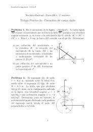
Tail Rotor Driveshaft Hanger
Tail Rotor Driveshaft Hanger
Tail Rotor Driveshaft Hanger
- No tags were found...

You also want an ePaper? Increase the reach of your titles
YUMPU automatically turns print PDFs into web optimized ePapers that Google loves.
BHT-212-CR&0of retainer does not align with notch of innercoupling, pull retainer out, rotate it 90 ° andreinstall. Repeat if necessary to obtainalignment. Install lock spring (4).11. Extend outer coupling (11) so seal (13)is against teeth of inner coupling (10). Coatinternal splines of outer coupling withlubricant (tube pack) (C-015) to 0.12 in.,Q.(3.048 mm) depth over top of spline teeth. Aworkaid may be fabricated (figure 65-6) toobtain depth of grease.12. Place small end of centering spring (3)on boss of plate (2). Install plate (2), spacer(5), and spring (3) into coupling and installretaining ring (1) (figure 65-28).-(Q13. Test quill as follows: Hold sleeve andturn coupling. There should be a very lightdrag caused by preload of oil seal and duplexbearings. Coupling and pinion should turnsmoothly.14. Tag tail rotor drive quill with date oflubrication and make an entry made incomponent historical record, if quill is to bereturned to stock.(CD`-'(-D15. When tail rotor drive quill is installed onhelicopter make an entry in helicopter log andflex couplings lubrication log (BHT-212-MM)with date of lubrication.(J10 (CDm-065-52. Painting.MATERIALS REQUIREDRefer to BHT-ALL-SPM for specification andsource.NUMBERNOMENCLATUREC-309 Methyl- Ethyl- Ketone(MEK)1. Clean external surfaces of input quillsleeve with MEK (C-309) and clean cloths. Donot allow MEK to contact seals.O-0_,c2. Mask seal (14, figure 65-28) at outboardend of quill.3. Refer to paragraph 65-44 for paintinginstructions applicable to input quill.65-00-00Rev.4 Page 79