Tail Rotor Driveshaft Hanger
Tail Rotor Driveshaft Hanger
Tail Rotor Driveshaft Hanger
- No tags were found...

Create successful ePaper yourself
Turn your PDF publications into a flip-book with our unique Google optimized e-Paper software.
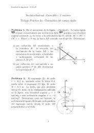
BHT-212-CR&015. Repair or replace shim plate (17, figure65-21) and shim (18) as follows:a. If original plating on shim plate (17)has worn through, apply brush cadmiumplating solution (C-108). Required dimensionsshall be met after plating (figure 65-27).2:acanU,-Co.COOmooNCO 0)}3'3.Coca1-+ +'°3(,3OHO000 Q-_-5-.0._5.-:b. Examine gearbox case (9) forwpmX.m.-.0reference dimension etched on shim and shimplate adjacent to applicable mounting surface.Record reference dimensions.C. Subtract 0.3542 to 0.3546 in. (8.99668to 9.00684 mm) from referenced dimensionon case (9) to give required thickness forshim (18).d. If a shim (18) of correct thickness is°`.0:xeCOOE(OD0(nnot on hand, grind a new blank shim torequired thickness determined in step c.Sides of shim shall be parallel within 0.0002in. (0.00508 mm). Do not cadmium plateshim (18).e. Subtract 5.2498 to 5.2503 in.(133.34492 to 133.35762 mm) fromreferenced dimension on case (9) to giverequired thickness for shim plate (17).f. If a shim plate (17) of correct thicknessis not on hand, grind a new blank shim plateto required thickness determined in step e.After grinding, countersink three holes 100° X0.250 to 0.260 in. (6.35 to 6.604 mm)diameter. Cadmium plate shim plate (17)using brush cadmium plating solution (C-108).After plating, sides of shim plate shall beparallel within 0.0002 in. (0.00508 mm) oninside 4.600 in. (116.84 mm) diameter, butplate may taper 0.0000 to 0.0005 in. (0.0 to0.0127 mm) on either or both sides outside4.600 in. (116.84 mm) diameter. Identify newshim plate by serial number of case (9) onwhich it is to be installed and shim platethickness. Use etching ink or equivalent.Neutralize acid, after marking, with water andbaking soda.16. Repair sleeve (38) as follows:a. Replace clinch nuts (39) if damaged orloose (BHT-ALL-SPM).'8'b. Replace sleeves which have excessivecorrosion damage (figure 65-24).ELL0C. Repair sleeves, which do not exceedallowable corrosion damage limits, as follows:(1) Polish out (within acceptable limits)any sharp edges which might damagepackings using abrasive cloth or paper (C-423). Finish smooth with crocus (C-500).(2) Immerse corroded sleeve in chromicacid (C-116) bath to completely removecorrosion products (BHT-ALL-SPM)..-.on"(+)+-'O,3(Do boo'.0Z-)°0CU!)v`-(CDeeeeeeeeeeeeeeeeeCAUTIONeeeeeeeeeeeseeeeCORROSION REMOVAL PROCESSSHALL BE MONITORED TOENSURE MACHINED DIMENSIONSARE MAINTAINED AND CADMIUM-o0PLATING IS NOT REMOVED FROMSTUDS.(3) Immediately after corrosion removalapply chemical film treatment to magnesiumalloy (refer to BHT-ALL-SPM).17. Repair output shaft (1) as follows:a. Polish out mechanical and corrosiondamage (within allowable limits specified infigure 65-26) with 400 grit abrasive cloth orpaper (C-423) to blend with surrounding areaand to effect a bottom radius of 1/2 in. (12.7mm).(°Da)) +L.m(Db. No rework is required in oil sealcontact area if depth of wear does not exceed0.002 in. (0.0508 mm) and groove is uniformand smooth. More severe damage may bereworked as follows providing such repairgives 100% cleanup: Grind seal diameter toa minimum diameter of 1.430 in. (36.322 mm)(figure 65-26). Reground area shall notextend into existing 0.062 in. (1.5748 mm)radius and blend into existing diameter with aminimum radius of 0.062 in. (1.5748 mm).Finished diameter shall be concentric withdiameter for roller bearings within 0.0015 in.(0.0381 mm) T.I.R. and surface finish shall be16 RMS or better.("m c(°O.00^-'U73-)3o 0--mE65-00-00Rev.4 Page 65