Suite 7.1 Manual - Audio Design Associates
Suite 7.1 Manual - Audio Design Associates
Suite 7.1 Manual - Audio Design Associates
You also want an ePaper? Increase the reach of your titles
YUMPU automatically turns print PDFs into web optimized ePapers that Google loves.
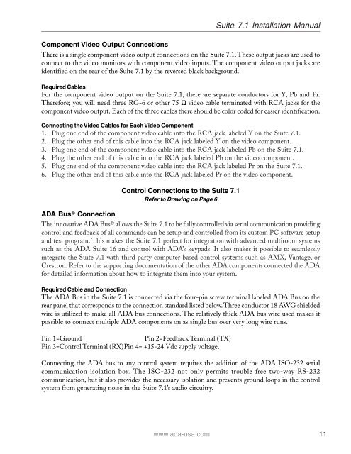
<strong>Suite</strong> <strong>7.1</strong> Installation <strong>Manual</strong><br />
Component Video Output Connections<br />
There is a single component video output connections on the <strong>Suite</strong> <strong>7.1</strong>. These output jacks are used to<br />
connect to the video monitors with component video inputs. The component video output jacks are<br />
identified on the rear of the <strong>Suite</strong> <strong>7.1</strong> by the reversed black background.<br />
Required Cables<br />
For the component video output on the <strong>Suite</strong> <strong>7.1</strong>, there are separate conductors for Y, Pb and Pr.<br />
Therefore; you will need three RG-6 or other 75 Ω video cable terminated with RCA jacks for the<br />
component video output. Each of the three cables there should be color coded for easier identification.<br />
Connecting the Video Cables for Each Video Component<br />
1. Plug one end of the component video cable into the RCA jack labeled Y on the <strong>Suite</strong> <strong>7.1</strong>.<br />
2. Plug the other end of this cable into the RCA jack labeled Y on the video component.<br />
3. Plug one end of the component video cable into the RCA jack labeled Pb on the <strong>Suite</strong> <strong>7.1</strong>.<br />
4. Plug the other end of this cable into the RCA jack labeled Pb on the video component.<br />
5. Plug one end of the component video cable into the RCA jack labeled Pr on the <strong>Suite</strong> <strong>7.1</strong>.<br />
6. Plug the other end of this cable into the RCA jack labeled Pr on the video component.<br />
Control Connections to the <strong>Suite</strong> <strong>7.1</strong><br />
Refer to Drawing on Page 6<br />
ADA Bus® Connection<br />
The innovative ADA Bus® allows the <strong>Suite</strong> <strong>7.1</strong> to be fully controlled via serial communication providing<br />
control and feedback of all commands can be setup and controlled from its custom PC software setup<br />
and test program. This makes the <strong>Suite</strong> <strong>7.1</strong> perfect for integration with advanced multiroom systems<br />
such as the ADA <strong>Suite</strong> 16 and control with ADA’s keypads. It also makes it possible to seamlessly<br />
integrate the <strong>Suite</strong> <strong>7.1</strong> with third party computer based control systems such as AMX, Vantage, or<br />
Crestron. Refer to the supporting documentation of the other ADA components connected the ADA<br />
for detailed information about how to integrate them into your system.<br />
Required Cable and Connection<br />
The ADA Bus in the <strong>Suite</strong> <strong>7.1</strong> is connected via the four-pin screw terminal labeled ADA Bus on the<br />
rear panel that corresponds to the connection standard listed below. Three conductor 18 AWG shielded<br />
wire is utilized to make all ADA bus connections. The relatively thick ADA bus wire used makes it<br />
possible to connect multiple ADA components on as single bus over very long wire runs.<br />
Pin 1=Ground Pin 2=Feedback Terminal (TX)<br />
Pin 3=Control Terminal (RX)Pin 4= +15-24 Vdc supply voltage.<br />
Connecting the ADA bus to any control system requires the addition of the ADA ISO-232 serial<br />
communication isolation box. The ISO-232 not only permits trouble free two-way RS-232<br />
communication, but it also provides the necessary isolation and prevents ground loops in the control<br />
system from generating noise in the <strong>Suite</strong> <strong>7.1</strong>’s audio circuitry.<br />
www.ada-usa.com 11


