PICAXE Manual Section 1 - TechnoPujades - Free
PICAXE Manual Section 1 - TechnoPujades - Free
PICAXE Manual Section 1 - TechnoPujades - Free
- No tags were found...

You also want an ePaper? Increase the reach of your titles
YUMPU automatically turns print PDFs into web optimized ePapers that Google loves.
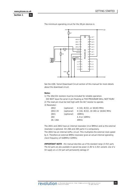
www.picaxe.co.uk<strong>Section</strong> 1 31GETTING STARTEDThe minimum operating circuit for the 28 pin devices is:5V4k7128out 7ADC 0227out 6ADC 1326out 5ADC 2425out 4ADC 3524out 312310k22kserial in 6serial out 7894MHz10in 0 11<strong>PICAXE</strong>-28232221201918out 2out 1out 0in 7in 11217in 6in 21316in 5in 31415in 4reset0VSee the USB / Serial Download Circuit section of this manual for more detailsabout the download circuit.Notes:1) The 10k/22k resistors must be included for reliable operation.DO NOT leave the serial in pin floating as THE PROGRAM WILL NOT RUN!2) The reset pin must be tied high with the 4k7 resistor to operate.3) Resonator:28X2 (optional) 4 (16), 8(32), or 10(40) MHz28X2-3V (optional) 4 (16), 8(32), 10 (40) or 16(64) MHz28X1 (optional) 16MHz28X4, 8 or 16MHz28 / 28A 4MHzThe 28X1 and 28X2 have an internal resonator (4 or 8MHz) and so the externalresonator is optional. On 28A and 28X parts it is compulsory.The 28X2 has an internal 4xPLL circuit. This multiplies the external clock speedby 4. Therefore an external 8MHz resonator gives an actual internal operatingclock frequency of 4x8MHz=32MHz.IMPORTANT NOTE - this manual describes use of the standard range (3-5V) parts.The X2 parts are also available in special low power (1.8V to 3.3V) variants. Use of a5V supply on a 3.3V part will permanently damage it!revolution(c) Revolution Education Ltd. Email: info@rev-ed.co.uk Web: www.rev-ed.co.ukVersion 6.9 07/2009All rights reserved.31