PICAXE Manual Section 1 - TechnoPujades - Free
PICAXE Manual Section 1 - TechnoPujades - Free
PICAXE Manual Section 1 - TechnoPujades - Free
- No tags were found...

You also want an ePaper? Increase the reach of your titles
YUMPU automatically turns print PDFs into web optimized ePapers that Google loves.
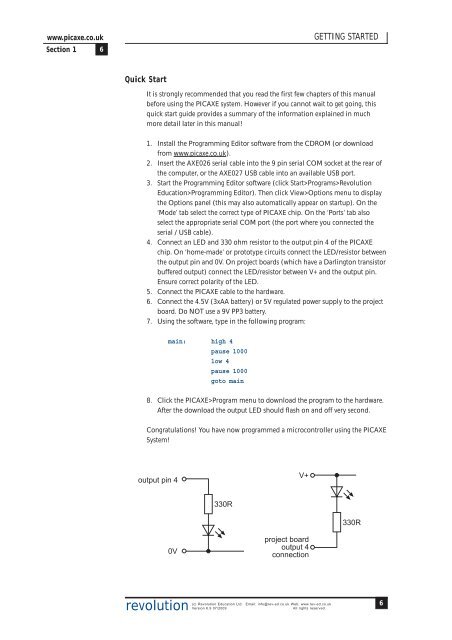
www.picaxe.co.uk<strong>Section</strong> 1 6GETTING STARTEDQuick StartIt is strongly recommended that you read the first few chapters of this manualbefore using the <strong>PICAXE</strong> system. However if you cannot wait to get going, thisquick start guide provides a summary of the information explained in muchmore detail later in this manual!1. Install the Programming Editor software from the CDROM (or downloadfrom www.picaxe.co.uk).2. Insert the AXE026 serial cable into the 9 pin serial COM socket at the rear ofthe computer, or the AXE027 USB cable into an available USB port.3. Start the Programming Editor software (click Start>Programs>RevolutionEducation>Programming Editor). Then click View>Options menu to displaythe Options panel (this may also automatically appear on startup). On the‘Mode’ tab select the correct type of <strong>PICAXE</strong> chip. On the ‘Ports’ tab alsoselect the appropriate serial COM port (the port where you connected theserial / USB cable).4. Connect an LED and 330 ohm resistor to the output pin 4 of the <strong>PICAXE</strong>chip. On ‘home-made’ or prototype circuits connect the LED/resistor betweenthe output pin and 0V. On project boards (which have a Darlington transistorbuffered output) connect the LED/resistor between V+ and the output pin.Ensure correct polarity of the LED.5. Connect the <strong>PICAXE</strong> cable to the hardware.6. Connect the 4.5V (3xAA battery) or 5V regulated power supply to the projectboard. Do NOT use a 9V PP3 battery.7. Using the software, type in the following program:main: high 4pause 1000low 4pause 1000goto main8. Click the <strong>PICAXE</strong>>Program menu to download the program to the hardware.After the download the output LED should flash on and off very second.Congratulations! You have now programmed a microcontroller using the <strong>PICAXE</strong>System!output pin 4V+330R330R0Vproject boardoutput 4connectionrevolution(c) Revolution Education Ltd. Email: info@rev-ed.co.uk Web: www.rev-ed.co.ukVersion 6.9 07/2009All rights reserved.6