PICAXE Manual Section 1 - TechnoPujades - Free
PICAXE Manual Section 1 - TechnoPujades - Free
PICAXE Manual Section 1 - TechnoPujades - Free
- No tags were found...

Create successful ePaper yourself
Turn your PDF publications into a flip-book with our unique Google optimized e-Paper software.
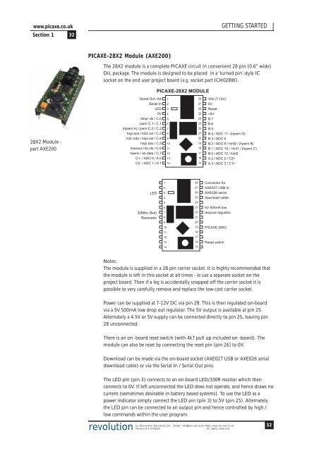
www.picaxe.co.uk<strong>Section</strong> 1 32GETTING STARTED<strong>PICAXE</strong>-28X2 Module (AXE200)The 28X2 module is a complete <strong>PICAXE</strong> circuit in convenient 28 pin (0.6” wide)DIL package. The module is designed to be placed in a ‘turned pin’ style ICsocket on the end user project board (e.g. socket part ICH028W).<strong>PICAXE</strong>-28X2 MODULE28X2 Module -part AXE200Serial Out / A4Serial InLED0Vtimer clk / C.0pwm C.1 / C.1(hpwm A) / pwm C.2 / C.2hspi sck / hi2c scl / C.3hi2c sda / hspi sdi / C.4hspi sdo / C.5hserout / kb clk / C.6hserin / kb data / C.7C1- / ADC 0 / A.0C2- / ADC 1 / A.112345678910111213142827262524232221201918171615VIN (7-12V)0VReset+5VB.7B.6B.5B.4 / ADC 11 / (hpwm D)B.3 / ADC 9B.2 / ADC 8 / hint2 / (hpwm B)B.1 / ADC 10 / hint1 / (hpwm C)B.0 / ADC 12 / hint0A.2 / ADC 2 / C2+A.3 / ADC 3 / C1+LED32MHz (8x4)Resonator12345678910112827262524232221201918Connector forAXE027 USB orAXE026 serialdownload cable5V 500mA lowdropout regulator<strong>PICAXE</strong>-28X2121713141615Reset switchNotes:The module is supplied in a 28 pin carrier socket. It is highly recommended thatthe module is left in this socket at all times - ie use a separate socket on theproject board. Then if a leg is accidentally snapped off the carrier socket it ispossible to very carefully remove and replace the low-cost carrier socket.Power can be supplied at 7-12V DC via pin 28. This is then regulated on-boardvia a 5V 500mA low drop out regulator. The 5V output is available at pin 25.Alternately a 4.5V or 5V supply can be connected directly to pin 25, leaving pin28 unconnected.There is an on -board reset switch (with 4k7 pull up included on -board). Themodule can also be reset by connecting the reset pin (pin 26) to 0V.Download can be made via the on-board socket (AXE027 USB or AXE026 serialdownload cable) or via the Serial In / Serial Out pins.The LED pin (pin 3) connects to an on-board LED/330R resistor which thenconnects to 0V. If left unconnected the LED does not operate, and hence draws nocurrent (sometimes desirable in battery based systems). To use the LED as apower indicator simply connect the LED pin (pin 3) to 5V (pin 25). Alternatelythe LED pin can be connected to an output pin and hence controlled by high /low commands within the user program.revolution(c) Revolution Education Ltd. Email: info@rev-ed.co.uk Web: www.rev-ed.co.ukVersion 6.9 07/2009All rights reserved.32