PICAXE Manual Section 1 - TechnoPujades - Free
PICAXE Manual Section 1 - TechnoPujades - Free
PICAXE Manual Section 1 - TechnoPujades - Free
- No tags were found...

Create successful ePaper yourself
Turn your PDF publications into a flip-book with our unique Google optimized e-Paper software.
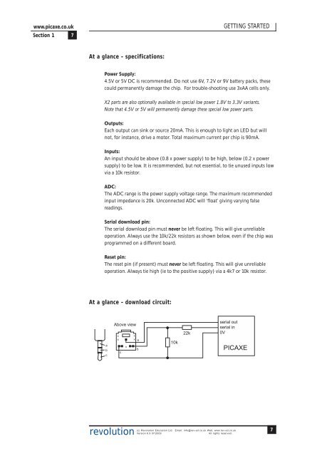
www.picaxe.co.uk<strong>Section</strong> 1 7GETTING STARTEDAt a glance - specifications:Power Supply:4.5V or 5V DC is recommended. Do not use 6V, 7.2V or 9V battery packs, thesecould permanently damage the chip. For trouble-shooting use 3xAA cells only.X2 parts are also optionally available in special low power 1.8V to 3.3V variants.Note that 4.5V or 5V will permanently damage these special low power parts.Outputs:Each output can sink or source 20mA. This is enough to light an LED but willnot, for instance, drive a motor. Total maximum current per chip is 90mA.Inputs:An input should be above (0.8 x power supply) to be high, below (0.2 x powersupply) to be low. It is recommended, but not essential, to tie unused inputs lowvia a 10k resistor.ADC:The ADC range is the power supply voltage range. The maximum recommendedinput impedance is 20k. Unconnected ADC will ‘float’ giving varying falsereadings.Serial download pin:The serial download pin must never be left floating. This will give unreliableoperation. Always use the 10k/22k resistors as shown below, even if the chip wasprogrammed on a different board.Reset pin:The reset pin (if present) must never be left floating. This will give unreliableoperation. Always tie high (ie to the positive supply) via a 4k7 or 10k resistor.At a glance - download circuit:abcAbove viewxxcxxxab10k22kserial outserial in0V<strong>PICAXE</strong>revolution(c) Revolution Education Ltd. Email: info@rev-ed.co.uk Web: www.rev-ed.co.ukVersion 6.9 07/2009All rights reserved.7