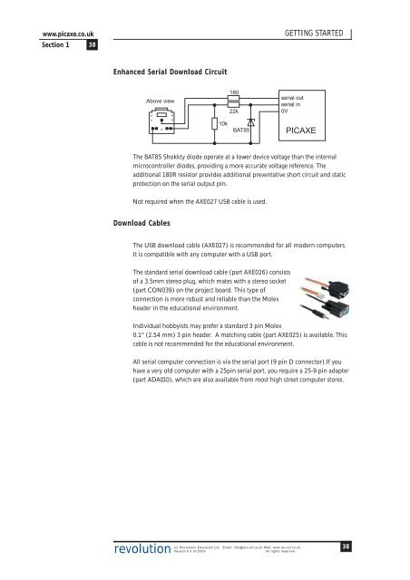
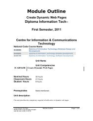
www.picaxe.co.uk<strong>Section</strong> 1 38GETTING STARTEDEnhanced Serial Download CircuitAbove viewxxxxx18022k10kBAT85serial outserial in0V<strong>PICAXE</strong>The BAT85 Shokkty diode operate at a lower device voltage than the internalmicrocontroller diodes, providing a more accurate voltage reference. Theadditional 180R resistor provides additional preventative short circuit and staticprotection on the serial output pin.Not required when the AXE027 USB cable is used.Download CablesThe USB download cable (AXE027) is recommended for all modern computers.It is compatible with any computer with a USB port.The standard serial download cable (part AXE026) consistsof a 3.5mm stereo plug, which mates with a stereo socket(part CON039) on the project board. This type ofconnection is more robust and reliable than the Molexheader in the educational environment.Individual hobbyists may prefer a standard 3 pin Molex0.1" (2.54 mm) 3 pin header. A matching cable (part AXE025) is available. Thiscable is not recommended for the educational environment.All serial computer connection is via the serial port (9 pin D connector).If youhave a very old computer with a 25pin serial port, you require a 25-9 pin adapter(part ADA010), which are also available from most high street computer stores.revolution(c) Revolution Education Ltd. Email: info@rev-ed.co.uk Web: www.rev-ed.co.ukVersion 6.9 07/2009All rights reserved.38
www.picaxe.co.uk<strong>Section</strong> 1 39GETTING STARTEDReset CircuitAll 18, 28 and 40 pin <strong>PICAXE</strong> have a ‘reset’ pin. This pin must be in the highcondition for the <strong>PICAXE</strong> microcontroller to function. If this pin is leftunconnected the microcontroller will not operate reliably. To tie this pin highconnect a 4.7k resistor between the reset pin and V+ supply rail (do not connectthe pin directly to V+, always use a resistor). A reset switch is optional, but highlyrecommended. This should be a ‘push to make’ type and connected between thereset pin and 0V.All 8, 14 and 20 pin <strong>PICAXE</strong> do not have a reset pin. Therefore to reset themicrocontroller the power supply must be disconnected and then reconnected.Note that, when using capacitors in your supply circuit, these capacitors may holdenough charge to keep the microcontroller powered for several seconds after thepower supply is disconnected.ResonatorDifferent <strong>PICAXE</strong> chips have internal or external (or both) options:<strong>PICAXE</strong> INTERNAL EXTERNAL08 4 -08M 4,8 -14M 4,8 -18 4 -18A 4,8 -18M 4,8 -18X 4,8 -20M 4,8 -20X2 4,8,16,32,64 -28A - 428X - 4,8,1628X1 4,8 4,8,1628X2 4,8 4 (=16), 8 (=32), 10 (=40)28X2-3V 4,8,16 4 (=16), 8 (=32), 10 (=40), 16 (=64)40X - 4,8,1640X1 4,8 4,8,1640X2 4,8 4 (=16), 8 (=32), 10 (=40)40X2-3V 4,8,16 4 (=16), 8 (=32), 10 (=40), 16 (=64)All 28 and 40 pin <strong>PICAXE</strong> can use an external resonator (the resonator is internalwithin the 08, 14, 20 and 18 pin <strong>PICAXE</strong>). Note that the internal resonatorwithin the 08,14,20 and 18 <strong>PICAXE</strong> is not quite as accurate as an externalresonator. Although this does not cause any issues with the majority of projects, ifa specialised project requires very high precision a 28 or 40pin <strong>PICAXE</strong> should beused.An 3 pin ceramic resonator is recommended when required. This device consistsof a resonator and two loading capacitors in a single 3 pin package. The centrepin is connected to 0V and the outer two pins to the two <strong>PICAXE</strong> resonator pins(the resonator can be used either way around).revolution(c) Revolution Education Ltd. Email: info@rev-ed.co.uk Web: www.rev-ed.co.ukVersion 6.9 07/2009All rights reserved.39