Vectra Genisys Service Manual - DJO Global
Vectra Genisys Service Manual - DJO Global
Vectra Genisys Service Manual - DJO Global
- No tags were found...

You also want an ePaper? Increase the reach of your titles
YUMPU automatically turns print PDFs into web optimized ePapers that Google loves.
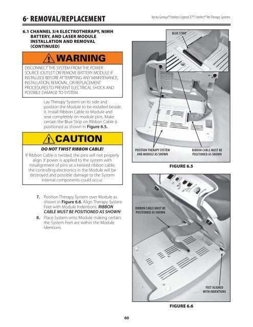
6- REMOVAL/REPLACEMENT6.1 CHANNEL 3/4 ELECTROTHERAPY, NIMHBATTERY, AND LASER MODULEINSTALLATION AND REMOVAL(CONTINUED)<strong>Vectra</strong> <strong>Genisys</strong>®/Intelect Legend XT®/ Intelect® Vet Therapy SystemsBLUE STRIPDISCONNECT THE SYSTEM FROM THE POWERSOURCE (OUTLET OR REMOVE BATTERY MODULE IFINSTALLED) BEFORE ATTEMPTING ANY MAINTENANCE,INSTALLATION, REMOVAL, OR REPLACEMENTPROCEDURES TO PREVENT ELECTRICAL SHOCK ANDPOSSIBLE DAMAGE TO SYSTEM.Lay Therapy System on its side andposition the Module to be installed besideit. Install Ribbon Cable to Module andseat completely on module pins. Makecertain the Blue Strip on Ribbon Cable ispositioned as shown in Figure 6.5.DO NOT TWIST RIBBON CABLE!If Ribbon Cable is twisted, the pins will not properlyalign. If power is applied to the system withmisalignment of pins or a twisted ribbon cable,the controlling electronics in the Module will bedestroyed and possible damage to the Systeminternal components could occur.POSITION THERAPY SYSTEMAND MODULE AS SHOWNFIGURE 6.5RIBBON CABLE MUST BEPOSITIONED AS SHOWN7.8.Position Therapy System over Module asshown in Figure 6.6. Align Therapy SystemFeet with Module Indentions. RIBBONCABLE MUST BE POSITIONED AS SHOWN!Place System onto Module making certainthe System Feet are within the ModuleIdentions.RIBBON CABLE MUST BEPOSITIONED AS SHOWNFEET ALIGNEDWITH INDENTIONSFIGURE 6.660