Vectra Genisys Service Manual - DJO Global
Vectra Genisys Service Manual - DJO Global
Vectra Genisys Service Manual - DJO Global
- No tags were found...
Create successful ePaper yourself
Turn your PDF publications into a flip-book with our unique Google optimized e-Paper software.
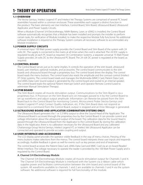
1- THEORY OF OPERATION<strong>Vectra</strong> <strong>Genisys</strong>®/Intelect Legend XT®/ Intelect® Vet Therapy Systems1.1 OVERVIEWThe <strong>Vectra</strong> <strong>Genisys</strong>, Intelect Legend XT and Intelect Vet Therapy Systems are comprised of several PC boardassemblies housed within a common enclosure. These assemblies each support a distinct function inthe product. The basic elements are User Interface, Control Board, Stim Board, Ultrasound Board, UltrasoundApplicator, and Power Supply Circuits.When a Module (Channel 3/4 Electrotherapy, NiMH Battery, Laser, or sEMG) is installed, the Control Boardsoftware automatically recognizes that a Module has been installed and prompts the installer to performcertain tasks, for verification of Module installed, to make the respective Module fully functional. No additionalsoftware installation is required as the Therapy System contains all necessary software to accommodate anyModule installation.1.2 POWER SUPPLY CIRCUITSA universal input 100 Watt power supply provides the Control Board and Stim Board of the system with 24volts DC. The supply is connected to the mains at all times when the cord is attached. The 24 VDC supply isregulated locally at each PC board as required. On Combination Systems, a separate universal 75 Watt PowerSupply provides 24 volts DC to the Ultrasound PC Board. The 24 volt DC power is regulated at the board, asrequired.1.3 CONTROL BOARDThe Control Board serves just as its name implies. It controls the operation of the stim board, ultrasoundboard, user interface, optional modules, and accessories. The control board communicates to the stimboards and ultrasound board through a proprietary bus. The control board drives the display. The controlboard reads the menu buttons. The control board also reads the amplitude and the contrast control (IntelectXT Only) systems. The control board reads and manages the Multimedia (MMC) Card, Patient Data Card,and sEMG Data Card. Sound output is generated by the control board and routed to an internal speaker.The control board reads the optional Patient Interrupt Switch and Operator Remote Control (used toadminister <strong>Manual</strong> Stimulation Therapy).1.4 STIM BOARDThe Stim Board creates all muscle stimulation output. Communications to the Stim Board is via aproprietary bus. A Processor on the Stim Board acts on messages passed to it by the Control Board toset up waveforms and adjust output amplitude. Information can likewise be passed from the StimBoard back to the Control Board for monitoring Current, Microcurrent Probe (<strong>Vectra</strong> <strong>Genisys</strong> andIntelect Legend XT only) Contact Quality indication, etc. If the Stim Board does not respond asexpected to a command from the Control Board, output is stopped and an Error Message is generated.1.5 ULTRASOUND BOARD AND APPLICATOR (COMBINATION SYSTEMS ONLY)The Ultrasound Board generates the 1 or 3.3 MHz output to drive the Sound Head of the Applicator. TheUltrasound Board is accessed through the proprietary bus by the Control Board. It can provide current andvoltage information about the ultrasound output of the board. The calibration data for the Sound Head ispassed through the Ultrasound Board from the Applicator to the Control Board. By storing the calibrationdata in the Applicator, there is no calibration necessary for the Ultrasound Board and any calibratedChattanooga Group <strong>Vectra</strong> <strong>Genisys</strong>, Intelect Legend XT, or Intelect Vet Ultrasound Applicator can beconnected and operated to provide accurate coupling and output.1.6 USER INTERFACE AND ACCESSORIESThe LCD display panel provides the operator visible feedback in the way of menu choices. Pressing of themenu buttons makes selections from the menus. The control board interprets these user inputs and respondsaccordingly. Audible feedback is given as well for events such as key presses and end of treatment.The control board accesses the Patient Data Card, sEMG Data Card and MMC Card via an on board Reader/Writer Interface. The voltage necessary to operate the reader is provided by the 100 Watt Power Supply and isregulated by the Control Board.A. Channel 3/4 Electrotherapy ModuleThe Channel 3/4 Electrotherapy Module creates all muscle stimulation output for Channels 3 and 4.The Channel 3/4 Electrotherapy Module is interfaced with the System via a ribbon cable whichsupplies power and facilitates communication between the stim board and control board of thesystem. All waveforms available to channels 1 and 2 are available to channels 3 and 4 via the systemsoftware. No additional software is required for full functionality of the module.2


