Vectra Genisys Service Manual - DJO Global
Vectra Genisys Service Manual - DJO Global
Vectra Genisys Service Manual - DJO Global
- No tags were found...

Create successful ePaper yourself
Turn your PDF publications into a flip-book with our unique Google optimized e-Paper software.
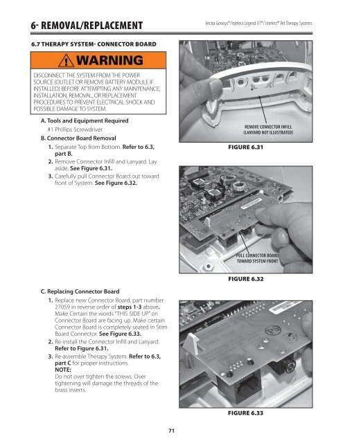
6- REMOVAL/REPLACEMENT<strong>Vectra</strong> <strong>Genisys</strong>®/Intelect Legend XT®/ Intelect® Vet Therapy Systems6.7 THERAPY SYSTEM- CONNECTOR BOARDDISCONNECT THE SYSTEM FROM THE POWERSOURCE (OUTLET OR REMOVE BATTERY MODULE IFINSTALLED) BEFORE ATTEMPTING ANY MAINTENANCE,INSTALLATION, REMOVAL, OR REPLACEMENTPROCEDURES TO PREVENT ELECTRICAL SHOCK ANDPOSSIBLE DAMAGE TO SYSTEM.A. Tools and Equipment Required#1 Phillips ScrewdriverB. Connector Board Removal1. Separate Top from Bottom. Refer to 6.3,part B.2. Remove Connector Infill and Lanyard. Layaside. See Figure 6.31.3. Carefully pull Connector Board out towardfront of System. See Figure 6.32.REMOVE CONNECTOR INFILL(LANYARD NOT ILLUSTRATED)FIGURE 6.31PULL CONNECTOR BOARDTOWARD SYSTEM FRONTFIGURE 6.32C. Replacing Connector Board1. Replace new Connector Board, part number27059 in reverse order of steps 1-3 above.Make Certain the words “THIS SIDE UP” onConnector Board are facing up. Make certainConnector Board is completely seated in StimBoard Connector. See Figure 6.33.2. Re-install the Connector Infill and Lanyard.Refer to Figure 6.31.3. Re-assemble Therapy System. Refer to 6.3,part C for proper instructions.NOTE:Do not over tighten the screws. Overtightening will damage the threads of thebrass inserts.FIGURE 6.3371